Table of Contents

Subscribe to Our Youtube Channel
Related Manuals for Charnwood W030


Summary of Contents for Charnwood W030
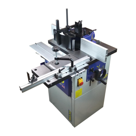
- Page 1 SPINDLE MOULDER OWNERS MANUAL MODEL: W030 Charnwood, Cedar Court, Walker Road, Hilltop Industrial Estate, Bardon Hill, Leicestershire, LE67 1TU Tel. 01530 516 926 Fax. 01530 516 929 email: sales@charnwood.net website: www.charnwood.net...
-
Page 2: Use Of The Machine
Forward These instructions are important, the information contained herein is essential for the correct build and operation of the machine and the safety of its operator. The machine is equipped with various safety devices to protect itself and the operator. However, these devices cannot cover all eventualities and a thorough understanding of spindle moulding techniques, good workshop practice plus the controls and operation of this machine are essential for your safety. - Page 3 4. Remove adjusting keys and spanners. Form a habit of checking to see that the keys and adjusting spanners are removed from the machine before switched it on. 5. Keep your work area clean. Cluttered areas and workbenches increase the chance of an accident.' 6.
-
Page 4: Specification
EXTRA RULES FOR SPINDLE MOULDERS 1. A spindle moulder should never be used by an untrained operator. Proper training is essential for the operator’s safety. 2. The machine must be properly maintained and the correct fitting of all guards checked. 3. - Page 5 Rating Light Trade: Suitable for professional woodworkers where the machine will not be in daily use. Mid-range machines with a heavier build and more power. Typically used by 2 or 3 people within a small business and also for the dedicated hobbyist with a larger budget. It is expected to be used up to the machines maximum limit with occasional long work periods.
- Page 6 Open the remaining cartons, unpack all the components and check everything is present. Cutter Hood Vertical Pressure Guard Tool Carriage Rubber Hood Bolts Plate Parts Tray Parts Feet Fence Horizontal Pressure Table Spindle Arbor Router Hood Halves Plate Inserts & Spacers Collet Cover Assembly...
- Page 7 Use 8 of the bolts, washers and nuts to join the 4 panels together. Fit all 8 bolts finger tight before tightening with a 10mm spanner. Having unbolted the machine from the pallet and removed any loose items which are packed around and inside it.
- Page 8 Use the remaining 4 bolts, washers and nuts to attach the base to the machine. Once all of the nuts and bolts are tight. Turn the machine the correct way up and stand it on the feet. Adjust the feet to level up if necessary.
- Page 9 Before fitting the sliding carriage it should be noted that the two outboard bearing wheels are mounted on eccentrics. Should it ever be necessary their position can be adjusted with the aid of a 14 mm spanner. Slide the sliding table on to the guide rail, ensuring the guide rollers engage with the channels running either side of the rail.
- Page 10 Place the crosscut fence with the open side face down and the plastic tip to the right. Slide the pivot block and the locking block onto the back side of the fence with the head of the bolt in the T-slot. The Locking block has a T- shaped foot plate, slide it into the slot in the table.
- Page 11 Here you can see the tapered end of the spindle. Locate the spindle lock on the right hand side of the machine. Rotate the tapered spindle slowly whilst pushing the locking bar inwards. When the lock engages the bar will slide in around 10mm and the spindle will be locked.
- Page 12 If the bolt holding the upper and tapered spindle together ever comes loose, it will be necessary to use the special spanner provided to hold the upper spindle in place whilst unlocking the top bolt. The router collet is mounted onto the tapered spindle in the same way.
- Page 13 Fit the 2 long bolts through the slots in the hood and then screw them into a pair of holes in the table. The hood can be fixed in different positions depending on the size of the work piece. The cover is hinged to provide quick access to the spindle to change the tooling.
- Page 14 Assemble the front guard and clamp. Fit the square bar into the hood cover and lock it with the thumbscrew. Slide the vertical hold down onto the square bar and lock it with the thumb screw. Fit the front spring guard into the end of the square bar and lock it with the thumb screw.
- Page 15 When stacking the spacers, ensure that the one with the roll pin is at the top of the stack. The pin engages with the slot in the top of the spindle. Not all of the spacers will be used at the same time.
-
Page 16: Changing Speeds
Changing Speeds The spindle moulder has 4 speeds. To change speed: Unscrew the knob and open this access door. (The machine is fitted with a micro switch and will not run when this door is open) Slacken off the locking lever Reduce the tension on the drive belt by moving this lever. - Page 17 Declaration of Conformity for CE Marking Charnwood Declare that Woodworking Vertical Spindle Moulder, Model W030 Conforms with the following Directives: Machinery Directive 2006/42/EC Low Voltage Directive 2006/95/EC And further conforms to the machinery example for which the EC type examination Certificate No.
-
Page 19: Parts List A
Parts List A Part No. Description Part No. Description Underprop Linking Plate Supporting Plate Hex Nut M6 Washer M6 Hex Bolt M6 x 16mm Hex Nut M6 Washer M6 Hex Bolt M6 x 16mm Guide Rail Hex Nut M8 Washer M8 Screw M8 x 10mm Power Plug Metric Bushing M16... -
Page 21: Parts List B
Parts List B Part No. Description Part No. Description Screw M6 x 16mm Circular Washer Driven Pully C' Ring 47mm Bearing 6204 Hex Bolt M5 x 12mm Washer M5 Nut Bush Screw M6 x 14mm Washer M6 Angle Plate Plate Cuneal Belt Screw M6 x 16mm Large Washer... - Page 23 Parts List C Part No. Description Part No. Description Adjusting Wheel Exhaustion Socket Guide Rack T-Shaped Bolt Screw M6 x 10mm Metal Plate Hex Bolt M5 x 12mm Rhombic Handgrip Aluminium Fence Turing Rack Locking Sheet Metal Spring Washer M8 Rhombic Handgrip Saucer C18A...
- Page 24 Updated October 2020 Charnwood, Cedar Court, Walker Road, Hilltop Industrial Estate, Bardon Hill, Leicestershire, LE67 1TU Tel. 01530 516 926 Fax. 01530 516 929 email: sales@charnwood.net website: www.charnwood.net...
Need help?
Do you have a question about the W030 and is the answer not in the manual?
Questions and answers