
Related Manuals for Holzworth Instrumentation HSX Series

Summary of Contents for Holzworth Instrumentation HSX Series
- Page 1 HSX SERIES Multi-Channel RF Synthesizers RoHS User Manual 1.14 Holzworth Instrumentation Inc. 2540 Frontier Ave., Suite 200 Boulder, CO 80301 USA www.holzworth.com...
- Page 2 This page intentionally left blank.
-
Page 3: Table Of Contents
2.1 CE CERTIFICATION ..................... 4 2.2 RoHS COMPLIANCE .................... 4 3.0 PRODUCT WARRANTY ..................4 4.0 CALIBRATION NOTICE ..................4 5.0 HSX SERIES CONFIGURATION GUIDE ..............5 5.1 CONFIGURATION SUMMARY ................5 5.2 HARDWARE CONFIGURATION ................6 5.2.1 NUMBER OF CHANNELS ................6 5.2.2 LOADED CHANNEL FREQUENCIES ............ -
Page 4: Introduction
Holzworth Instrumentation Inc. This User’s Manual is a quick reference guide for use with the Holzworth HSX Series Multi- Channel RF Synthesizer products. Refer to section 5 for specific configuration details with regards to the HSX Series hardware. -
Page 5: Hsx Series Configuration Guide
Internal channels offer better than -110 dB of channel-channel isolation. The HSX Series is a unique platform allowing the user to specify custom configurations for a COTS product. Units are loaded with anywhere from 1 to 4 channels (up to 6GHz). The HSX Series provides industry leading phase noise and spectral purity performance, as well as exceptionally high output power dynamic range from +20 to -110 dBm. -
Page 6: Hardware Configuration
Additional factory loaded options are also defined in the “Loaded Options” designator on the front panel. These options further customize the HSX Series to an application and are loaded at the factory when the unit is initially built. Accessories are external to the HSX platform and can be ordered separately. -
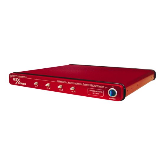
Page 7: Mechanical Configuration
5.3 MECHANICAL CONFIGURATION The HSX Series comes in a 1U high, rack mountable chassis. The example shown is of a 4 channel unit (front panel configuration may vary). A universal rack mount bracket kit is an available accessory (Part No.: RACK-1U or RACK2-1U). Mechanical dimensions are listed in inches (and millimeters). -
Page 8: Environmental Specifications
20 min 20 C (ambient temp. dependent) Specifications are subject to change per the discretion of Holzworth Instrumentation, Inc *NOTE: Amplitude accuracy may vary when operated outside of channel operating temperature specified in section 6.3. Internal channel temperature should be monitored using the ":TEMP?"... -
Page 9: Application Gui Operation
6.1 APPLICATION GUI OPERATION The Holzworth HSX Series GUI can be run on any Windows PC. There is no installation required. Simply double click the executable file to launch the GUI. The latest version can be downloaded by navigating to the URL below: http://www.holzworth.com/software/Synthesizers/HSX/HSX9000.zip... -
Page 10: Usb, Rs-232, And Gpib Communication
Synthesizers, the user must determine the COM port the instrument is using. The COM port associated with the USB connection to the HSX9000 can be identified by using the application GUI as shown above or via the Windows Device Manager. www.holzworth.com Page HSX Series User Manual 1.14 10 of 32... -
Page 11: Identify Instrument Com Port & Usb Troubleshooting
"Hardware Sound" STEP TWO Under "Devices and Printers," select Device Manager STEP THREE Under Ports (COM & LPT) locate COM port associated with the HA7062C (identified as "USB Serial Port") www.holzworth.com Page HSX Series User Manual 1.14 11 of 32... -
Page 12: Gpib Communication
5. Carriage Return: Carriage return (ASCII Code 13) 6. Pinout: PIN Label Label Label TX (Response Output) RX (Instruction Input) 6.2.2 GPIB COMMUNICATION The Holzworth HSX9000 is GPIB capable. GPIB configuration commands are listed in Appendix A. www.holzworth.com Page HSX Series User Manual 1.14 12 of 32... -
Page 13: Ethernet Communication
'Device IP Address' field and then press the Connect button. If the connection is successful the window above 'Devices' will turn green and display the IP address. www.holzworth.com Page HSX Series User Manual 1.14 13 of 32... -
Page 14: Direct Pc Connection (Dhcp Mode)
5. Power cycle the instrument when prompted. When the instrument fully powers back on (5-10 second power up) it will come up with the static IP settings and can be connected to the LAN. www.holzworth.com Page HSX Series User Manual 1.14 14 of 32... -
Page 15: Troubleshooting Ethernet Connections
5. Begin by querying with the :IP:STATUS? command. Change status and/or re- configure the static network settings as necessary. 6. Power cycle the HSX9000 if prompted. Any status change from DHCP to Static or vice versa will require a power cycle. www.holzworth.com Page HSX Series User Manual 1.14 15 of 32... -
Page 16: Miscellaneous Ethernet Troubleshooting
('Obtain IP address automatically') and reset the synthesizer to DHCP using either method in the previous two sections. 6. Make a direct Ethernet connection from the PC to the synthesizer bypassing any routers or network switches. www.holzworth.com Page HSX Series User Manual 1.14 16 of 32... - Page 17 The PC IP address will default to 169.254.xxx.xxx and the subnet address will default to 255.255.0.0. 7. Close and re-launch the application GUI. Attempt to establish a connection to the HSX9000. 8. For further assistance please contact Holzworth Support. www.holzworth.com Page HSX Series User Manual 1.14 17 of 32...
-
Page 18: Hardware
7.0 HARDWARE The HSX Series Multi-Channel RF Synthesizers are CW work horses. They are designed to do a very good job of providing highly stable, phase coherent signals with pure spectrums and highly accurate output power amplitude control. 7.1 RF OUTPUT The RF Output ports are labeled and positioned sequentially from left to right on the front panel of the instrument. -
Page 19: Reference Output
FIX command is sent, it > +5.00dBm will remain in the 10dB state and not allow power levels outside of this state) Table 2: Atten. States Table 1: Atten. Mode Descriptions www.holzworth.com Page HSX Series User Manual 1.14 19 of 32... -
Page 20: Hardware Input/Output Configuration
7.3 HARDWARE INPUT/OUTPUT CONFIGURATION The HSX Series ships standard with region-specific AC power cord as well as the cables necessary for USB and Ethernet communication with the instrument. REAR PANEL DESCRIPTION SPECIFICATION Reference Output Port Connector Type SMA, 50ohm Output Frequency 10/100MHz ±10Hz... -
Page 21: Ac Power Supply
Contact Holzworth directly for product support. A list of US Sales Representatives and non-US Distribution partners are listed on the Holzworth website. Holzworth Instrumentation Sales Support Phone: +1.303.325.3473 (option 1) Email: sales@holzworth.com Holzworth Instrumentation Technical Support Phone: +1.303.325.3473 (option 2) Email: support@holzworth.com www.HOLZWORTH.com www.holzworth.com Page HSX Series User Manual 1.14 21 of 32... -
Page 22: Appendix A: Ascii Control Of Hsx Synthesizer
APPENDIX A: ASCII Control of HSX Synthesizer The following commands can be used to modify settings on the individual synthesizer channels of the HSX Series. NOTE: For the following commands, n stands for the channel number. HSX SERIES PROGRAMMING COMMANDS FREQUENCY SETTINGS COMMAND :CHn:FREQ:<value><suffix>... - Page 23 EXAMPLE :CH2:PWR:MODE:FIX RESPONSE Power Mode Set to FIXED, Attenuator set to XdB NOTE: X = value corresponding to current set power level per the table in section 7.2.4 PHASE SETTINGS www.holzworth.com Page HSX Series User Manual 1.14 23 of 32...
- Page 24 Query Channel Maximum Phase Offset Setting for Current Output DESCRIPTION Frequency EXAMPLE :CH2:PHASE:MAX? RESPONSE 719.96002200 degrees COMMAND :CHn:PHASE:RES? Query Channel Maximum Phase Offset Resolution Setting for DESCRIPTION Current Output Frequency EXAMPLE :CH2:PHASE:RES? RESPONSE 0.04394287 degrees www.holzworth.com Page HSX Series User Manual 1.14 24 of 32...
- Page 25 RESPONSE Empty string or the list of errors encountered COMMAND :TEMP? DESCRIPTION Query instrument average internal temperature EXAMPLE :TEMP? RESPONSE 40.21 COMMAND :CHn:TEMP? DESCRIPTION Query specific channel temperature (n = Ch #) EXAMPLE :CH3:TEMP? RESPONSE 40.11 www.holzworth.com Page HSX Series User Manual 1.14 25 of 32...
- Page 26 RESPONSE “Internal 100MHz” or “External 10MHz” COMMAND :REF:PLL? DESCRIPTION Query status of the PLL EXAMPLE :REF:PLL? “1 PLL Locked, 0 errors” or “0 PLL Unlocked, Insufficient RF RESPONSE Power, 'x' errors” or “0 PLL Disabled” www.holzworth.com Page HSX Series User Manual 1.14 26 of 32...
- Page 27 COMMUNICATION SETTINGS – General COMMAND *IDN? DESCRIPTION Query device information EXAMPLE *IDN? RESPONSE Holzworth Instrumentation, HSX9004A, #041, Ver:2.13 COMMAND :COMM:RESPOND:<value> DESCRIPTION Set Ethernet, USB, and RS-232 response status RANGE ON <or> OFF EXAMPLE :COMM:RESPOND:ON RESPONSE Respond to every command COMMAND :COMM:RESPOND?
- Page 28 DESCRIPTION Set Instrument Subnet Address EXAMPLE :IP:SUBNET:255.255.255.255 RESPONSE Subnet address changed COMMAND :IP:SUBNET? DESCRIPTION Query Instrument Subnet Address EXAMPLE :IP:SUBNET? RESPONSE 255.255.255.255 COMMUNICATION SETTINGS - GPIB Configuration COMMAND :GPIB:ADDR:<value> DESCRIPTION Set Instrument GPIB Address www.holzworth.com Page HSX Series User Manual 1.14 28 of 32...
- Page 29 GPIB only responds to queries or GPIB responds with every RESPONSE command Setting :GPIB:RESPOND:ON will ensure every command receives a response over GPIB. The default factory setting is :GPIB:RESPOND:OFF, which ensures only query commands receive a response. USER NOTES www.holzworth.com Page HSX Series User Manual 1.14 29 of 32...
- Page 30 USER NOTES www.holzworth.com Page HSX Series User Manual 1.14 30 of 32...
- Page 31 Page HSX Series User Manual 1.14 31 of 32...
- Page 32 All rights reserved. Holzworth Instrumentation Inc. 2540 Frontier Ave., STE 200 Boulder, Colorado 80301 USA +1.303.325.3473 www.HOLZWORTH.com Version 1.13 January 2020 www.holzworth.com Page HSX Series User Manual 1.14 32 of 32...
Need help?
Do you have a question about the HSX Series and is the answer not in the manual?
Questions and answers