Advertisement
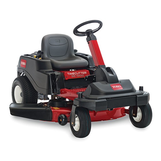
TimeCutter
Model No. SW TimeCutter Models
Setup
Loose Parts
Use the chart below to verify that all parts have been shipped.
Procedure
1
2
3
4
5
6
7
Note: Determine the left and right sides of the machine from the normal operating position.
© 2016—The Toro® Company
8111 Lyndale Avenue South
Bloomington, MN 55420
®
SW Riding Mower
Description
No parts required
Rear hitch
Bolt (5/16 x 1 inch)
Locknut (5/16 inch)
Steering wheel
Top cover
Locknut
Rear cover
Screws
Seat assembly
Seat rod
Hairpin cotter pins
Spacers (certain models only)
Grass deflector (if not installed)
No parts required
Ignition key
Hose coupling (not included with CE
models)
Operator's Manual
Engine Owner's Manual (non-Toro
engines)
KeyChoice® key (blue)
Register at www.Toro.com.
Form No. 3393-925 Rev C
Qty.
–
Connect the battery.
1
2
Install the rear hitch.
2
1
1
1
Install the steering wheel.
1
2
1
1
Install the seat assembly.
2
2
1
Install the grass deflector.
–
Check the mower adjustment.
1
1
1
Complete the setup.
1
1
Original Instructions (EN)
All Rights Reserved *3393-925* C
Printed in the USA
RELEASED Ver-C ©Toro 2016
Setup Instructions
Use
Advertisement
Table of Contents

Related Manuals for Toro TimeCutter SW Series


Summary of Contents for Toro TimeCutter SW Series
- Page 1 Ignition key Hose coupling (not included with CE models) Operator's Manual Complete the setup. Engine Owner’s Manual (non-Toro engines) KeyChoice® key (blue) Note: Determine the left and right sides of the machine from the normal operating position. © 2016—The Toro® Company Register at www.Toro.com.
- Page 2 (Figure g028437 Figure 2 1. Bolts 2. Locknuts G018395 g018395 Figure 1 1. Negative battery cable 4. Negative battery post cap 2. Wing nut 5. Carriage bolt 3. Washer 6. Negative battery post RELEASED Ver-C ©Toro 2016...
- Page 3 3. Install the steering wheel and top cover to the steering column with the locknut (Figure 4. Torque the locknut between 36.6 and 44.7 N-m (27 and 33 ft-lb). 5. Install the steering-wheel cover. g027887 Figure 5 1. Back cover 2. Screws RELEASED Ver-C ©Toro 2016...
- Page 4 (Figure g027723 g028383 Figure 6 g028383 Figure 8 3. Hairpin cotter 1. Seat assembly 1. Plastic connector in seat 2. Wire harness 2. Spacers 4. Seat rod with hairpin cotter installed frame hole RELEASED Ver-C ©Toro 2016...
- Page 5 Ignition key Grass deflector (if not installed) Hose coupling (not included with CE models) Procedure Operator's Manual Engine Owner’s Manual (non-Toro engines) If the grass deflector is not installed, remove it from the KeyChoice ® key (blue) packaging and install it onto the mower deck. Refer to your Operator’s Manual for the correct procedure to install the grass...
- Page 6 Notes: RELEASED Ver-C ©Toro 2016...
- Page 7 Notes: RELEASED Ver-C ©Toro 2016...
- Page 8 RELEASED Ver-C ©Toro 2016...
Need help?
Do you have a question about the TimeCutter SW Series and is the answer not in the manual?
Questions and answers