Table of Contents
Advertisement
Advertisement
Table of Contents

Subscribe to Our Youtube Channel
Related Manuals for Cane Creek Helm MKII


Summary of Contents for Cane Creek Helm MKII
- Page 1 SUS PENS ION FORK IN ST RUC T I O N M ANUAL...
- Page 2 This is the lens we look through when we conceive, design, test and manufacture Cane Creek components. We look to the rider – to ourselves – on the bike and ask, “How will this improve the ride?”...
-
Page 4: Table Of Contents
Table of Contents 04 ..Safety Warning Information / Tools Needed 06 ..Fork Features Overview 07 ..Crown Race Installation/Steer Tube Cutting 08 ..Star Nut/Stem Installation and Headset Preload 09 ..Front Brake and Cable Guide Screw/Cover Installation 10 .. - Page 5 Tools Needed For Installation: fork ever loses oil, air or makes unusual noises, stop riding and have • Saw for cutting steerer the fork inspected by a Cane Creek • Crownrace setter (Recommended Authorized Suspension Service Center Cane Creek part code HST005) or call the Cane Creek Customer •...
-
Page 6: Safety Warning Information / Tools Needed
Tools Needed Congratulations on the purchase of your Cane Creek Helm Fork. Cane Creek has been supplying revolutionary suspension technology to the bicycle market since 2005. Based on a foundation of precision quality and cutting-edge innovation, our forks and rear shocks represent the pinnacle of high- performance bicycle suspension systems. -
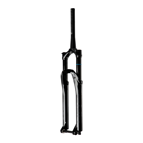
Page 7: Fork Features Overview
Fork Features Overview Fork Chasis Information Wheel Spacing Boost 110mm 15mm Axle Diameter 180mm Minimum Brake caliper specific adapter Brake Connection Post Mount Rotor Size needed for larger rotors. Axle to Crown (Axle to crown will change 553mm for 27.5 573mm for 29/27.5”+ proportionally to travel change) Measured at 160mm travel... - Page 8 Crown Race Install/Steer Tube Cutting Crown Race Install: After installing a headset into the bicycle frame, install the crown race included with the headset onto the fork according to the headset manufacturers instructions. Steerer Tube Cutting: Measure the steerer tube twice and cut to length according to the stem manu- facturers instructions.
-
Page 9: Star Nut/Stem Installation And Headset Preload
Star Nut/Stem Install and Headset Preload Star Nut Installation: Use a star nut setter tool to install a star nut into the steerer tube at a depth of 15mm. 15mm Stem Installation and Headset Preload: Install fork into frame and stem on steerer tube. -
Page 10: Front Brake And Cable Guide Screw/Cover Installation
Front Brake and Cable Guide Install ation Front Brake and Cable Guide Screw/Cover Installation: Install brake caliper according to the brake manufacturer’s instructions. Route the front disc brake hose or cable housing on the inside of the lower fork leg through the disc brake housing guide , fasten the cable housing into the brake line holder using a 2.5mm allen wrench. -
Page 11: Bolt-On Axle Installation
Bolt-On Axle Installation 1. Remove Bolt-On axle from fork by turning counter clock-wise with a 5mm hex wrench and slide the axle out of the fork. 2. Install front wheel into the dropouts and insert the Bolt-On axle with text “THIS SIDE UP” facing towards the head tube through the dropout. -
Page 12: D-Loc Axle Installation
D-Loc Axle Installation 1. Remove D-LOC axle from fork by opening the cam lever, then moving the axle lock latch to the “unlocked” position and slide the axle out of the fork. 2. Install front wheel into the dropouts and insert the D-LOC axle with text “THIS SIDE UP”... -
Page 13: Damper Adjustments
Damper Adjustments Compression Damping: Compression damping controls how easily the fork compresses under impacts. Low Speed Compression: Is used to manage traction and chassis Low Speed stabilization. LSC adjustment eliminates Compression pedal induced “bob”, influences small bump sensitivity, reduces brake dive and determines how the bike will react to weight changes. - Page 14 Damper Adjustments Rebound Rebound Damping: Rebound damping controls the speed at which the fork will return to normal height after a compression cycle. To adjust, turn adjuster on the bottom of the right side leg labeled Rebound. Turn clockwise to increase damping (Slower fork return speed), turn counterclockwise to decrease damping (Faster fork return speed).
-
Page 15: Air Spring Set Up
Air Spring Set Up Setting Sag is a crucial part of set up as it affects the ride height and head angle of bicycle. Positive and negative air chambers are manually equalized... adding or removing air is a two step process (1. - Page 16 Air Spring Set Up WARNING: The fork can become lowered when applying downward force while the negative air equalizer button is pressed, falsely lowering the travel of the fork as more air volume is moved from the positive chamber to the negative chamber. Wiper Seal If this occurs, press negative air chamber equalizer button down...
- Page 17 Increase air pressure and equalize Too much. negative chamber. Just Right. Too little. For sag recommendations and troubleshooting contact Cane Creek Cycling Components customer service at 1-828-641-9560. Recommended Air Pressure: We recommend inflating the Helm fork with air pressure equal to 30- 40% of your body weight (in lbs) in psi.
-
Page 18: Air Volume Adjustment
• 30mm Wrench all of the fork’s travel prematurely, • Shock Pump a reduction of volume should be performed. Cane Creek’s air volume reduction system allows any rider to achieve their desired “bottomless” feel without the need for additional materials. The system uses a static piston that is positioned on an indexed rod. - Page 19 Air Volume Adjustment 3./4. 3. Remove air valve assembly and unthread the air volume piston wing nut. Wing Nut 4. Install the air volume piston to Air Volume desired reduction point and fasten Piston the air volume piston wing nut. 5.
-
Page 20: Air Internal Travel Adjustment
ADJUSTMENT Follow these steps carefully to avoid foul assembly, warranty void, or serious injury. If you do not feel confident performing this procedure, contact a professional bike mechanic or a Cane Creek authorized Service Center. *For a detailed step by step video of this process, visit www.canecreek.com... - Page 21 Air Internal Travel Adjustment 2. Pressing the charge button down, release air from the top of fork *Verify that all air is removed from the fork in both the positive and negative air chambers by pressing negative chamber equalizer button REMOVE while releasing air from the positive chamber on the top of the fork.
- Page 22 Air Internal Travel Adjustment 5. Using your hand, push on compression rod nut and rebound knob assembly to disengage seals on lowers. Now, completely unthread compression rod nut and rebound knob assembly and remove from fork. 6. Lay fork face down on something protective.
- Page 23 Air Internal Travel Adjustment 9. Pull air seal head upward exposing compression rod assembly. 10./11. 10. Pull top out bumper towards air seal head to expose nylon washer. 11. Clip travel reducer onto the White Nylon compression rod between the white Washer nylon washer and air piston.
- Page 24 Air Internal Travel Adjustment 12. Reinstall air seal head past the retaining ring bore and install retaining ring. Start with one end of the retaining ring seated in the bore and work in a circle to install. It is extremely important to ensure the clip is fully seated in to the bore.
-
Page 25: Coil Spring Set Up
Coil Spring Set Up 1. Move the sag ring indicator to the wiper seal of the fork according to the illustration. Set sag with damper compression settings fully open and coil preload fully open to prevent influence of factors other than the spring rate during this procedure. - Page 26 Coil Spring Set Up 3. Step off bicycle and measure the sag O-ring movement distance. Sag should be set approximately 10-25% of the total fork travel. Too much. Just Right. 4. If sag used is 20-25% or greater, Too little. consider adding preload to the spring by turning the adjuster clockwise.
-
Page 27: Coil Spring Rate Change
Contact your local dealer or visit canecreek.com for a coil spring purchase. Cane Creek offers extra soft (red), soft (black), medium (green), and firm (blue) spring rates. Tools required: • T10 Torx Wrench, T10 Torx •... - Page 28 Coil Spring Rate Change 3. Using a 30mm wrench, unscrew the spring preload assembly. 30mm wrench 4. 4. Using your hand, remove the existing spring. Pull spring out...
- Page 29 Coil Spring Rate Change 5. Apply grease to the new spring and insert the spring into the stanchion. Grease spring with general purpose bike grease 6. Apply 243 Blue Loctite to the threads of the spring preload assembly and reinstall the spring preload assembly with a torque wrench to 36Nm and reinstall the preload adjustment knob.
-
Page 30: Coil Internal Travel Adjustment
Coil Internal Travel Adjustment Cane Creek Helm Coil forks are preset from the factory, but travel can be changed internally in 10mm increments between 160mm, 150mm, 140mm, and 130mm travel if desired. WARNING: READ ALL STEPS BEFORE PERFORMING TRAVEL ADJUSTMENT Follow these steps carefully to avoid foul assembly, warranty void, or serious injury. - Page 31 Coil Internal Travel Adjustment 2. Using a 13mm wrench, loosen the 2/3. compression rod nut on the coil 13mm wrench spring side of the lower leg DO NOT UNTHREAD COMPLETELY. 18mm wrench 3. Using an 18mm wrench, loosen rebound knob assembly on damper side leg.
- Page 32 Coil Internal Travel Adjustment 5. Lay fork face down on a protective flat surface. Grabbing the lowers and the upper legs with a hand on each, pull and separate. *LEAVE LOWERS LAYING FACE DOWN TO PREVENT THE LOSS OF OIL. If oil is lost from the lowers, Helm forks use 15w Motorex fork oil, 5ml in coil spring leg, 7ml in damper leg.
- Page 33 Coil Internal Travel Adjustment 7. Pull coil seal head upward and completely remove the compression rod assembly from the stanchion tube. THE DELRIN GLIDE RING CAN SEPARATE FROM THE SPRING PERCH. ENSURE ALL PARTS OF THE COMPRESSION ROD ASSEMBLY ARE REMOVED DURING TRAVEL CHANGE.
- Page 34 Coil Internal Travel Adjustment 8. Change the travel to the location to the desired position, choosing 130mm Travel 130mm Travel between 160mm, 150mm, 140mm, 140mm Travel 140mm Travel and 130mm travel options by positioning the spring perch on one 150mm Travel 150mm Travel of the four travel settings.
- Page 35 Coil Internal Travel Adjustment 10. Reinstall lowers on fork by feeding 10a. fully extended compression rod and damper rod into holes in the lowers. Use Blue Loctite on the threads of the two assemblies. Tighten rebound knob assembly with an 18mm wrench to 7Nm. Tighten compression rod nut with a 13mm wrench to 5Nm.
-
Page 36: Service And Maintenance Schedule
Rides torque and axle tension. Remove lowers, clean and inspect bushings and seals, change oil bath. Full fork air spring and damper rebuild performed by a Cane Creek Authorized Service Center. Follow these recommended service intervals for best performance. -
Page 37: Warranty Information
Cane Creek warrants, improper use. Should it be determined, by to the original retail owner of each new Cane Creek in its sole and final discretion, Cane Creek suspension product, that the that a Cane Creek suspension product is... - Page 38 When making a claim under this Limited • Rubber moving parts Warranty you will be required to provide to • Stripped threads/bolts (aluminum, an authorized Cane Creek Warranty Center: titanium, magnesium or steel) 1. The Product (or the affected part) and • Upper tubes (stanchions) 2.
- Page 39 Cane Creek Cycling Components 355 Cane Creek Rd Fletcher North Carolina 28732 1.828.641.9560 canecreek.com AAG0632_Rev2...
Need help?
Do you have a question about the Helm MKII and is the answer not in the manual?
Questions and answers