Table of Contents
Advertisement
Advertisement
Table of Contents

Related Manuals for Cane Creek Helm


Summary of Contents for Cane Creek Helm
- Page 1 SUS PENS ION FORK IN ST RUC T I O N M ANUAL...
-
Page 3: Table Of Contents
Table of Contents 04 ..Safety Warning Information 05 ..Tools Needed 06 ..Fork Features Overview 07 ..Crown Race Installation 08 ..Steerer Tube Cutting and Star Nut Installation 09 ..Stem Installation and Headset Preload 10 ..Front Brake and Cable Guide Screw/Cover Installation 11 .. - Page 4 SERIOUS INJURY OR bicycle. Before installing and using DEATH. Do not modify your bike frame your new front fork, carefully read this or fork. Use only genuine Cane Creek owner’s manual to learn the correct Helm parts. installation and adjustment procedures of this fork.
-
Page 5: Tools Needed
Tools Needed Specialized tools and materials are needed for the installation of your Cane Creek parts. Installation of Cane Creek parts by a qualified bicycle mechanic is highly recommended. Tools Needed For Installation: • Saw for cutting steerer • Crownrace setter (Recommended Cane Creek part code HST005) •... -
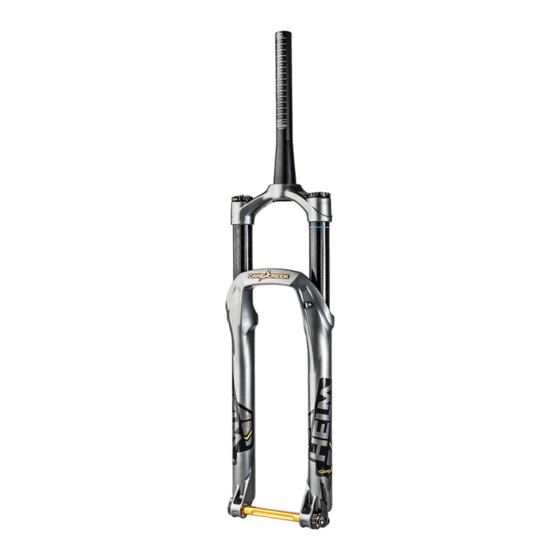
Page 6: Fork Features Overview
Fork Features Overview Wheel Spacing Boost 110mm Brake Connection Post Mount 180mm Rotor Size Adaptor Needed For 200mm Rotor Max 65mm wide by 714mm tall. WARNING: Due Tire Clearance Maximum Tire to wide variations in rim and tire widths, always Size check tire clearance before riding. -
Page 7: Crown Race Installation
Crown Race Installation Crown Race Installation: After installing a headset into the bicycle frame, install the crown race included with the headset onto the fork according to the headset manufacturers instructions. -
Page 8: Steerer Tube Cutting And Star Nut Installation
Steerer Tube Cutting and Star Nut Installation Steerer Tube Cutting: Measure the steerer tube twice and cut to length according to the stem manufacturers instructions. WARNING: Do not install more than 30mm of spacers below the stem. Star Nut Installation: Use a star nut setter tool to install a star nut into the steerer tube at a depth of 15mm. -
Page 9: Stem Installation And Headset Preload
Stem Installation and Headset Preload Stem Installation and Headset Preload: Install fork into frame and stem on steerer tube. Tighten headset and stem according to the manufacturer’s instructions. -
Page 10: Front Brake And Cable Guide Screw/Cover Installation
Front Brake and Cable Guide Install ation Front Brake and Cable Guide Screw/ Cover Installation: Install brake caliper according to the brake manufacturer’s instructions. Route the front disc brake hose or cable housing on the inside of the lower fork leg through the disc brake housing guide. -
Page 11: D-Loc Axle Installation
D-Loc Axle Installation 1. Remove D-LOC axle from fork by opening the cam lever, then moving the axle lock latch to the “unlocked” position and slide the axle out of the fork. Cam Lever Latch Lock 2. Install front wheel into the dropouts and insert the D-LOC axle with text “THIS SIDE UP”... - Page 12 D-Loc Axle Installation 3. Lock the D-LOC axle lock latch. 4. Use the tension adjuster to adjust the axle’s clamp strength and close axle lever to complete wheel installation. WARNING: An improperly tensioned axle, a lever not completely engaged or a lever not positioned in the upward closed Tension Adjuster position could result in disengagement...
-
Page 13: Air Spring
Air Spring Set Up Setting Sag is a crucial part of set up as it affects the ride height and head angle of bicycle. Follow these steps carefully. 1. Unscrew AIR top cap to reveal air valve and thread on shock specific pump. - Page 14 Air Spring Set Up WARNING: The fork can become lowered when applying downward force while the negative air equalizer button is pressed, falsely lowering the travel of the fork as more air volume is moved from the positive chamber to the negative chamber. Wiper Seal If this occurs, press negative air chamber equalizer button down...
- Page 15 Components customer service at To little. 1-800-234-2725 Recomended Air Pressure: We recommend inflating the Helm fork with air pressure equal to half of your body weight (in lbs) in psi. Example 150lb rider weight, start with 75psi and adjust from there if necessary.
-
Page 16: Air Volume Adjustment
• 30mm Wrench all of the fork’s travel prematurely, • Shock Pump a reduction of volume should be performed. Cane Creek’s air volume reduction system allows any rider to achieve their desired “bottomless” feel without the need for additional materials. The system uses a static piston that is positioned on an indexed rod. - Page 17 Air Volume Adjustment 3. Remove air valve assembly and 3./4. unthread the air volume piston wing nut. 4. Reposition air volume piston to Wing Nut desired reduction and refasten the air volume piston wing nut. Air Volume Piston 5. Reinstall air valve assembly, torque to 36Nm, and set sag.
-
Page 18: Damper Adjustments
Damper Adjustments Compression Damping: Compression damping controls the how easily the fork compresses under impacts. Low Speed Compression: Low Speed Is used to manage traction and chassis Compression stabilization. LSC adjustment eliminates pedal induced “bob”, influences small bump sensitivity, reduces brake dive and determines how the bike will react to weight changes. - Page 19 Damper Adjustments Rebound Damping: Rebound Rebound damping controls the speed at which the fork will return to normal height after a compression cycle. To adjust, turn adjuster on the bottom of the right side leg labeled Rebound. Turn clockwise to increase damping, turn counterclockwise to decrease damping.
-
Page 20: Internal Travel Adjustment
Internal Travel Adjustment Cane Creek Helm fork travel is preset Travel Reducers from the factory, but travel can be changed internally in 10mm increments if desired. Two travel reducers are included with every HELM fork. Tools required: • 13mm Wrench •... - Page 21 Internal Travel Adjustment 2. Pressing the charge button down, release air from the top of fork *Verify that all air is removed from the fork in both the positive and negative air chambers by pressing negative chamber equalized button while releasing air from the positive REMOVE REMOVE chamber on the top of the fork.
- Page 22 Internal Travel Adjustment 5. Using your hand, tap lightly on compression rod nut and rebound knob assembly to disengage seals on lowers. Now, completely unthread compression rod nut and rebound knob assembly and remove from fork. 6. Lay fork face down on something protective.
- Page 23 Internal Travel Adjustment 9. Pull air seal head upward exposing compression rod assembly. Avoid lifting air piston past threads on upper legs. The o-ring of the air piston could be damaged if it is lifted past the threads on the stanchion.
- Page 24 Internal Travel Adjustment 12. Reinstall air seal head with 22mm wrench. Torque air seal head to 16Nm. DO NOT OVER TIGHTEN 13. Press charge button and pull compression rod up to 50% extension. 14. Reinstall lowers on fork, feed compression rod and damper rod into holes in lowers.
-
Page 25: Service And Maintenance Schedule
Rides torque and axle tension. Remove lowers, clean and inspect bushings and seals, change oil bath. Full fork air spring and damper rebuild performed by a Cane Creek Authorized Service Center. Follow these recommended service intervals for best performance. -
Page 26: Warranty Information
SUSPENSION PRODUCTS not transferable to subsequent owners. Subject to the limitations, terms and This warranty is void if the Cane Creek conditions here of, Cane Creek warrants, suspension product is subjected to to the original retail owner of each new... - Page 27 Warranty Information improper maintenance, crash, misuse THIS IS THE ONLY WARRANTY MADE or collision. Subject to the terms and BY CANE CREEK ON ITS SUSPENSION conditions of this warranty, leaking PRODUCTS AND COMPONENTS, AND seals will be replaced within 90 days THERE ARE NO WARRANTIES THAT from the original date of purchase.
- Page 28 Cane Creek Cycling Components 1.800.234.2725 355 Cane Creek Rd canecreek.com Fletcher North Carolina 28732 info@canecreek.com...
Need help?
Do you have a question about the Helm and is the answer not in the manual?
Questions and answers