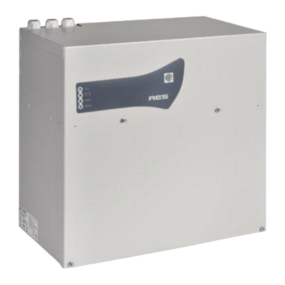
SLAT AES Series Operating Instructions Manual
Emergency power supply
Hide thumbs
Also See for AES Series:
- Operating instructions manual (52 pages) ,
- Operating instructions manual (48 pages) ,
- Operating instructions manual (40 pages)
Advertisement
Available languages
Available languages
Quick Links
Advertisement

Summary of Contents for SLAT AES Series
- Page 1 NOTICE D’UTILISATION 180160015Ba NOT160016Ba Edition : 0719...
- Page 5 1.1 Tableau des correspondances Les courants indiqués sont les courants (I ) à puissance nominale de sortie. 1.2 Spécifications environnementales 1.3 Spécifications électriques d’entrée et de sortie...
- Page 6 2.1 Fixation et dimensions des coffrets (dim : LxHxP mm) 2.2 Batteries 2.3 Intégration des produits clients...
- Page 7 Reportez-vous aux documents Siemens pour plus de détails techniques et sur le fonctionnement des transpondeurs indiqués dans les tableaux ci-dessus.
- Page 8 3.1 Plan de raccordement Le collier fourni avec tous les produits permet la fixation du câble secteur au niveau du bornier secteur. Attention, des ouvertures sont prévues à différents emplacements dans les coffrets, veillez à n’utiliser que ces derniers. Ne pas créer d’ouvertures supplémentaires sous peine de dysfonctionnement de l’appareil et de non reprise sous garantie.
- Page 9 * Vous devez raccorder toutes les résistances fournies avec le transpondeur aux borniers de toutes les entrées (même inutilisées) et conformément à la notice du transpondeur. Les résistances sont à raccorder à l’extrémité du câble.
- Page 10 * Vous devez raccorder toutes les résistances fournies avec le transpondeur aux borniers de toutes les entrées (même inutilisées) et conformément à la notice du transpondeur. Les résistances sont à raccorder à l’extrémité du câble. Reportez-vous aux documents Siemens pour plus de détails techniques sur la raccordement des transpondeurs indiqués dans les tableaux et schémas ci-dessus.
- Page 11 3.2 Sections de raccordement Reportez-vous aux documents Siemens pour plus de détails techniques sur le raccordement des transpondeurs indiqués dans le tableau ci-dessus.
- Page 13 5.1 Alarmes...
- Page 14 5.2 Récapitulatif des équipements disponibles 7.1 Alimentation...
- Page 15 7.2 Carte 5 départs fusiblés...
- Page 17 BEDIENUNGSANLEITUNG...
- Page 21 1.1 Vergleichstabelle Die angegebenen Stromwerte sind Ströme (I ) bei Ausgangsnennleistung. 1.2 Angaben zu den umweltbezogenen Spezifikationen 1.3 Angaben zu den elektrischen Ein- und Ausgängen...
- Page 22 2.1 Befestigung und Abmessungen der Gehäuse (Abm.: BxHxT mm) 2.2 Batterien 2.3 Integration der Produkte des Anwenders...
- Page 23 Ziehen Sie für weitere technische Einzelheiten und zur Funktionsweise der in den obigen Tabellen aufgeführten Transponder die Dokumente von Siemens zurate.
- Page 24 3.1 Anschlussplan Verkabelung mit der Karte mit 5 Sicherungsausgängen Verkabelung mit 2 Karten mit 5 Sicherungsausgängen Mit der mitgelieferten Schelle kann das Netzkabel an Stelle der Netzklemmleiste befestigt werden. Achtung! Die im Gehäuse vorgesehenen Öffnungen müssen verwendet werden. Bohren Sie keine zusätzlichen Öffnungen in das Gehäuse.
- Page 25 * Sie müssen den mitgelieferten Widerstand mit dem Transponder an die Eingangsklemmen und gemäß der Bedienungsanleitung des Transponders anschließen. Die Widerstände werden am Kabelende angeschlossen.
- Page 26 * Sie müssen den mitgelieferten Widerstand mit dem Transponder an die Eingangsklemmen und gemäß der Bedienungsanleitung des Transponders anschließen. Die Widerstände werden am Kabelende angeschlossen. Ziehen Sie für weitere technische Einzelheiten zu den in den obigen Tabellen aufgeführten Kontakten der Transponder die Dokumente von Siemens zurate.
- Page 27 3.2 Anschlussquerschnitte Ziehen Sie für weitere technische Einzelheiten zum Anschluss der in der obigen Tabelle aufgeführten Transponder die Dokumente von Siemens zurate.
- Page 29 5.1 Alarme...
- Page 30 5.2 Zusammenfassung der verfügbaren Systeme...
- Page 31 7.1 Stromversorgung 7.2 Karte mit 5 Sicherungsausgängen...
- Page 33 OPERATING INSTRUCTIONS...
- Page 37 1.1 Correspondence table The currents (I ) shown are at rated output power. 1.2 Environmental specifications 1.3 Electrical input and output specifications...
- Page 38 2.1 Mounting and cabinet dimensions (dim.: WxHxD mm) 2.2 Batteries 2.3 Customer product integration...
- Page 39 Refer to the Siemens documents for more technical details and transponder operation as shown in the tables above.
- Page 40 3.1 Connection diagram The cable tie included with all the products allows the mains cable to be secured to the mains terminal strip. N C : N orm ally C losed N O : N orm ally O pened Important: The openings provided in the cabinet must be used. Do not create additional openings, as doing so may cause the device to malfunction and voids the warrant.
- Page 41 * You must connect the provided resistance with the transponder to the input terminals and according to the transponder‘s manual. The resistances are connected at the end of the cable...
- Page 42 * You must connect the provided resistance with the transponder to the input terminals and according to the transponder‘s manual. The resistances are connected at the end of the cable Refer to the Siemens documents for more technical details of the transponder contacts shown in the tables above.
- Page 43 3.2 Connection sections Refer to the Siemens documents for more technical details on the transponder connection shown in the table above.
- Page 45 5.1 Alarms...
- Page 46 5.2 Summary of available equipment 7.1 Alimentation 7.2 5 outputs board with fuses...
- Page 47 Produits Numéro de DoP Années de marquage CE Produkte DoP nummer Jahre der CE markierung Products DoP number CE marking years...


Need help?
Do you have a question about the AES Series and is the answer not in the manual?
Questions and answers