Table of Contents
Advertisement
CPB-516
2P-0055
OPERATION AND MAINTENANCE
MANUAL
TRAILED TRACK SYSTEM (TTS)
30 & 35 Series (167" Track, Including: 30-1612, 35-1813, 35-2011, 35-2211, 35-2212,
35-2511 & 35-2512)
30 & 40 Series (187" Track, Including: 30-1611, 40-2512 & 40-2513)
40 & 45 Series (236" Track, Including: 40-1511, 40-1512, 45-1815 & 45-1816,
Excludes: 45-1814)
Advertisement
Table of Contents

Related Manuals for CAMSO TTS 30 Series


Summary of Contents for CAMSO TTS 30 Series
- Page 1 CPB-516 2P-0055 OPERATION AND MAINTENANCE MANUAL TRAILED TRACK SYSTEM (TTS) 30 & 35 Series (167” Track, Including: 30-1612, 35-1813, 35-2011, 35-2211, 35-2212, 35-2511 & 35-2512) 30 & 40 Series (187” Track, Including: 30-1611, 40-2512 & 40-2513) 40 & 45 Series (236” Track, Including: 40-1511, 40-1512, 45-1815 & 45-1816, Excludes: 45-1814)
- Page 2 This page intentionally left blank CPB-516 Operation and Maintenance Manual – TTS 30-40-45 Series (excluding 45-1814) (01-2020)
-
Page 3: Table Of Contents
Table of 1.0 FOREWARD ........................... 4 Literature Information ...................... 4 Maintenance Intervals ..................... 4 Camso Product Identification Number ................4 2.0 SAFETY ..........................5 2.1 Important Safety Information ....................5 3.0 GENERAL INFORMATION ..................... 5 3.1 Technical Description ......................5 3.2 Track System Components .................... -
Page 4: Table Of 1.0 Foreward
(on edge of track carcass) If a serialized axle is also provided by Camso, it will also have a plate installed in the center of the axle. Track part # and serial # are embossed into the edge of the track carcass for ease of identification. -
Page 5: Safety
3.0 GENERAL INFORMATION 3.1 Technical Description Camso Trailed Track Systems allow machines to move on muddy and soft soils which have limited carrying capacity. The wide supporting surface of the track system also reduces soil compaction. -
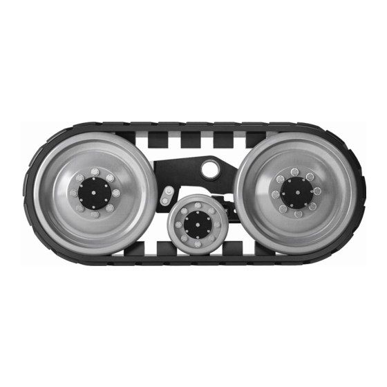
Page 6: Track System Components
TTS uses Camso rubber tracks, specifically designed for pull-behind applications to provide: • Reduced vibration during transport • Lower turning resistance • Minimal soil disturbance • Long life The patented undercarriage design incorporates independent movement of the midrollers both front-rear and side-side delivering: •... - Page 7 Midroller Oscillation Cavity, 125 ml of universal trandraulic fluid (1 per undercarriage). Plug torque is 25 ft-lb Front and rear Idler hubs, (34Nm) 500 ml of universal trandraulic fluid (4 Hubs per undercarriage). Plug torque is 25 ft-lb (34Nm) Detensioning bolt Midroller hubs, 215 ml of Alignment Bolt 221 ft-lb (300 and jam nut...
- Page 8 Frame The main frame consists of a weldment or casting which hangs the front alignment assembly and rear tension link. The front alignment yoke and rear tension link are cast members, allowing for close tolerance machining and structural rigidity. Axles Front and rear axles are machined from the yoke castings, allowing for dimensional stability and few moving parts.
-
Page 9: Specifications And Dimensions
1303 3.4 Weight Limitations Camso track systems are limited to operating weights as listed in the table below. Do not exceed these weight limitations or track system damage or component failure may result. Total Scale Weight Capacity per Set (2 undercarriages) -
Page 10: Transport Limitations
3.6 Minimum Turning Radius Limitations Camso track systems operate best when running straight or in gentle turns. If a track system is pivot or spot turned, the opportunity exists for soil and dirt to be ingested into the system. -
Page 11: Operational Guidelines
• Rubber tracks have not been designed for extended use on the road. Camso is not responsible for track and system damage resulting for extended road use. Long road periods and/or roading at higher than recommended maximum speeds may cause premature wear or failure of the track or wheels and is not a warrantable condition. -
Page 12: Track Break-In Procedures
• If a machine becomes stuck, clear away as much material from the undercarriage as possible prior to pulling the machine out. • Avoid short turning radius turns and operation(s) especially when loaded. Spot turning creates debris ingestion and can also induce high torque loading in the system. •... -
Page 13: Track System Installation
WARNING Danger of crushing. Use suitable lifting devices (capacity at least 9000 lbs (4100Kg)), wear safety equipment and observe the safety rules. If using a fork lift use for handling operations, be careful not to damage the rubber track. Metal chains or cables are not recommended 4.2 Track System Installation Clean the implement thoroughly before proceeding with the installation. - Page 14 IMPORTANT Safety of the installation depends on the right operation in lifting and supporting the machine. Check the work area thoroughly and work in a level area. Respect safe operating practices, operate in conditions of enough light. Make sure the free spaces of the work area are suitable for the dimensions of the parts to be handled and for the lifting equipment maneuvers.
- Page 15 Grease these areas Lightly grease machined surface of center pivot pin and insert into the receiver end of the axle. Rotate the pin to align the rear mounting hole in the receiver pin. Install the bolt and locknut provided with the kit. Torque pin bolt and lock nut to 130 Nm (96 ft-lbs) .
- Page 16 Check and re-torque all wheel lug bolts as follows: Wheel bolt diameter Torque (Nm) Torque (ft-lbs) M16 (Midrollers) M20 (Idlers) CPB-516 Operation and Maintenance Manual – TTS 30-40-45 Series (excluding 45-1814) (01-2020)
-
Page 17: Scheduled Maintenance
Make sure that mobile parts with safe fixed positioning are locked and the tools used for maintenance are suitable for the type of service Camso is not responsible for direct or indirect damages occurred to people or things due to tampering, removal or modification of the safety devices, or caused by modifications of the machine without any previous authorization. -
Page 18: Maintenance Schedule
5.3 Maintenance Schedule Daily Weekly Monthly Annual 5 years or Task or 10h or 50h or 100h or 500hr 2000hr Inspect and clean track system Inspect track condition Check track alignment Inspect for oil leaks on idler, midroller hubs and pivot axles Grease undercarriage and track system pivot points Check track tension... -
Page 19: Weekly Maintenance Or Every 50 Working Hours
5.3.2 Weekly maintenance or every 50 working hours 1. Grease undercarriage and track system pivot points. Main center pin (2 shots of grease) Main frame pin (2 shots of grease) Tension link pin (2 shots of grease) CPB-516 Operation and Maintenance Manual – TTS 30-40-45 Series (excluding 45-1814) (01-2020) - Page 20 Main center pivot pin (4 shots of grease- grease fitting in end of center pivot pin) Main frame pin/rear (2 shots of grease) Tension link pivot pin (2 shots of grease) Doghouse pivot (2 shots of grease) Alignment arm pivot pin (2 shots of grease) CPB-516 Operation and Maintenance Manual –...
-
Page 21: Monthly Maintenance Or Every 100 Working Hours
5.3.3 Monthly maintenance or every 100 working hours 1. Check track tension. Refer to chart below for recommended setting. Refer to “Adjusting track tension” for additional information. No tension adjustment is required if spring module is functioning properly. Tensioner TTS Series Spring Setting Type No preload-onset of compression less one... -
Page 22: Routine Maintenance
6.0 ROUTINE MAINTENANCE 6.1 Check Track Alignment 1. Prior to checking track alignment the implement should be empty and spring tensioning mechanism set properly with no pre-load. 2. Pull the implement on a flat surface for a suitable time frame, allowing the belts to relax and move freely on the undercarriage rollers. - Page 23 3. Tighten the special cap screw on the opposite side of the same undercarriage to specification. (Cap screw torque is 300 Nm (221 ft-lb). Tighten cap screw loosened in step 2 to the same specification. Note: A single full turn is the standard increment during adjustment.
-
Page 24: Track System Inspection
6.3 Track system inspection Track System Inspect track system for material build-up on frames and wheels. Clean material from undercarriage. Material build up on idler wheels can affect track alignment and produce additional heat buildup. Idlers and midrollers Check the general condition of the idlers and midrollers, in particular on inner flange surface of the wheels. -
Page 25: Track Removal
6.5 Track Removal 1. Place the undercarriage on a level surface and loosen the bolts on the outer idler wheels hubs. Undercarriage may not need removal from the implement to be worked on. 2. Locate the tension module between the rear idlers. Locate the jam nut on the upper rear tension link assembly. -
Page 26: Troubleshooting
Dealer 8.0 ADDITIONAL INFORMATION Additional information on Camso track systems, tracks, and our other products may be found at http://www.Camso.co. For any questions or corrections regarding this manual, please email us at Ag.Productsupport@camso.co . You can also contact our Customer Service Desk @ 317-671-7327 or 1-844-226-7624. -
Page 27: Warranty Certificate
9.0 WARRANTY CERTIFICATE CPB-516 Operation and Maintenance Manual – TTS 30-40-45 Series (excluding 45-1814) (01-2020) - Page 28 Camso.co Camso © 2019...
Need help?
Do you have a question about the TTS 30 Series and is the answer not in the manual?
Questions and answers