Table of Contents
Advertisement
Available languages
Available languages
Quick Links
Advertisement
Chapters
Table of Contents

Related Manuals for HomeMatic HMW-Sen-SC-12-FM


Summary of Contents for HomeMatic HMW-Sen-SC-12-FM
- Page 1 Installations- und Bedienungsanleitung (S. 4) Installation and operating manual (p. 18) RS485 Schließerkontakt 12 Eingänge Unterputzmontage: RS485 12-channel shutter contact for flush mounting: HMW-Sen-SC-12-FM...
- Page 2 1. Ausgabe Deutsch 06/2009 Dokumentation © 2009 eQ-3 Ltd., Hong Kong Alle Rechte vorbehalten. Ohne schriftliche Zustim- mung des Herausgebers darf dieses Handbuch auch nicht auszugsweise in irgendeiner Form reproduziert werden oder unter Verwendung elektronischer, me- chanischer oder chemischer Verfahren vervielfältigt oder verarbeitet werden.
-
Page 3: Table Of Contents
Allgemeine Systeminformation zu HomeMatic ......7 Allgemeine Hinweise zum Bussystem ..8 Allgemeine Hinweise zur Installation . -
Page 4: Hinweise Zu Dieser Anleitung
Hinweise zu dieser Anleitung Lesen Sie diese Anleitung sorgfältig, bevor Sie ihre HomeMatic-Komponenten in Betrieb nehmen. Bewahren Sie die Anleitung zum späteren Nach- schlagen auf! Wenn Sie das Gerät anderen Per- sonen zur Nutzung überlassen, übergeben Sie auch diese Bedienungsanleitung. -
Page 5: Funktion
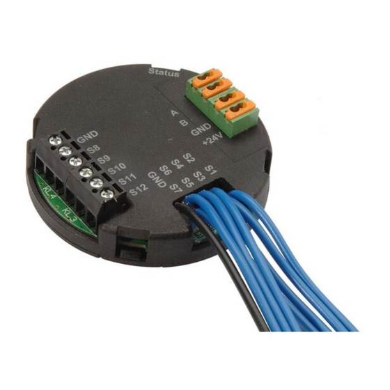
Arbeiten in Installationsbereichen mit Netzspannung dürfen nur durch eine Elektro-Fachkraft (nach VDE 0100) erfolgen. Dabei sind die geltenden Unfallverhü- tungsvorschriften zu beachten. Bei Nichtbeachtung der Installationshinweise kön- nen Brand- oder andere Gefahren entstehen. Betreiben Sie das Gerät nur in Innenräumen und vermeiden Sie den Einfluss von Feuchtigkeit, Staub sowie Sonnen- oder andere Wärmebestrahlung. - Page 6 Zustand mit (z.B. Kontakt offen oder geschlossen). • Umfangreiche Konfigurationsmöglichkeiten über die HomeMatic-Zentrale • Unterputz-Montage A B C D (A) - Geräte-LED (B) - Bus A (C) - Bus B (D) - Masse Busspannungsversorgung (E) - Busspannungsversorgung + 24 V (F) - Herausgeführte Schaltkontakt-Eingänge S1...S7...
-
Page 7: Allgemeine Systeminformation Zu Homematic
über Programme möglich, wobei ein Timer zur Hilfe genommen werden muss. Allgemeine Systeminformation zu HomeMatic Dieses Gerät ist Teil des HomeMatic-Haussteuersy- stems. Alle Geräte werden mit einer Standardkonfiguration ausgeliefert. Darüber hinaus ist die Funktion des Gerätes über ein Programmiergerät und Software konfigurierbar. -
Page 8: Allgemeine Hinweise Zum Bussystem
Allgemeine Hinweise zum Bussystem 5.1 Allgemeine Hinweise zur Installation Grundsätzlich kann man die Anschlüsse der HMW-Komponenten in zwei Gruppen einteilen. In die Lastseite und in die Steuerseite (24 V- Span- nungsversorgung, Tastereingänge, RS485-Bus). Der Schließerkontakt-Sensor verfügt aufgrund seiner Aufgabe, die Schaltzustände der angeschlossenen Kontakte zu erfassen, lediglich über die Steuerseite. -
Page 9: Topologie Des Bussystems
Module z. B. einer Etage dimensioniertes 24 V-Netzteil. Wenn eine zentrale Programmierung und Steuerung über die HomeMatic-Zentrale erfolgen soll, sollten die HMW-Busleitungen der einzelnen Module sowie die vom Steuer-PC bzw. einer Zentrale kommende Leitung an einem unter räumlichen Gesichtspunkten günstigen Ort zusammengeführt werden, um eine... -
Page 10: Installation
Fehlersuche zu vereinfachen. Üblicher- weise ist dies der Raum, in dem die Zentrale des HomeMatic-Systems installiert wird. Installation Das Gerät besitzt für die Kontakteingänge S1...S7 fle- xible Verbindungsleitungen (0,5 mm ) mit Aderend- hülsen. Entfernen Sie vor dem Anschluss die Gum- mikappen, die auf die Aderendhülsen aufgesteckt... - Page 11 Die Eingänge sind nur für den Anschluss potentialfreier Schaltkontakte geeignet. Eingänge nicht mit 230-V-Netzspannung verbinden! Schließen Sie die Schaltkontakte jeweils zwischen GND und dem jeweiligen Eingang (S1, …) an. Die maximale Leitungslänge vom Schalt- kontakt zum Modul ist je nach verwendeter Leitung unterschiedlich.
- Page 12 S1...7: blau GND: schwarz...
-
Page 13: Funktions-Zuordnung Der Schaltkontakt
Anschluss der Spannungsversorgung an den Klemmen. Funktions-Zuordnung der Schaltkontakt-Eingänge Die 12 Schaltkontakt-Eingänge des HMW-Sen-SC- 12-FM lassen sich nur über die HomeMatic-Zentrale anderen HomeMatic-Komponenten zuordnen, es sind keine direkten Verknüpfungen mit anderen Komponenten möglich. Da dieses Gerät keine Bedienelemente besitzt, erfolgt jegliche Bedienung und Konfiguration über die Bedienoberfläche „HomeMatic WebUI”, die als... -
Page 14: Anlernen Von Schaltkontakt-Eingängen
HomeMatic-Wired-Geräte über das HomeMatic WebUI zu aktivieren. 7.2 Verwendung des Gerätes Nach dem Anlernen und der Konfiguration an der HomeMatic-Zentrale kann das Gerät zur Erstellung von Programmabläufen verwendet werden. Diese Programmabläufe sind zentral gesteuerte Geräte- verknüpfungen, bei denen zwei oder mehrere Geräte über die zwischengeschaltete HomeMatic-Zentrale... -
Page 15: Wartung Und Reinigung
es besteht keine direkte Verbindung zwischen den einzelnen Geräten. Die Zentrale übernimmt die gesamte Steuerung. Daher ist das Gerät in den zugehörigen Kanallisten zur Erstellung einer direkten Verknüpfung nicht gelistet. Ist bei der Anwendung nur die Information über den aktuellen Zustand eines Schaltkontaktes interes- sant, so kann dieser im Untermenü... -
Page 16: Technische Daten
Technische Daten Kommunikation: Schnittstelle: RS485-Bus Protokoll: HomeMatic Wired Steuereingänge: 12 unabhängige Kontaktein- gänge, massebezogen (Schutzkleinspannung) Grenzwerte des Kontaktwiderstandes: Kontakt geöffnet: R ≥ 80 kΩ Kontakt geschlossen: R ≤ 5 kΩ Spannungsversorgung: 24 V (20 V bis 30V) / DC Stromaufnahme: 20 mA Zugelassene Leitungsquerschnitte für:... - Page 17 Entsorgungshinweis: Gerät nicht im Hausmüll entsorgen! Elektronische Geräte sind entsprechend der Richt linie über Elektro- und Elektronik- Altgeräte über die örtlichen Sammelstellen für Elektronik-Alt geräte zu entsorgen. Das CE-Zeichen ist ein Freiverkehrszeichen, das sich ausschließlich an die Behörden wendet und keine Zusicherung von Eigen- schaften beinhaltet.
- Page 18 English edition 06/2009 Documentation © 2009 eQ-3 Ltd., Hong Kong All rights reserved. This manual may not be reprodu- ced in any format, either in whole or in part, nor may it be duplicated or edited by electronic, mechanical or chemical means, without the written consent of the publisher.
- Page 19 Function ......21 General information about the HomeMatic system ....23 General information about the bus system . 24 General information about installation .
-
Page 20: Information About This Manual
Information about this manual Read this manual carefully before starting to use your HomeMatic components. Keep the manual so you can refer to it at a later date should you need to. If you hand over the device to other persons for use, please hand over the opera- ting manual as well. -
Page 21: Function
Only qualified electricians (to VDE 0100) are permitted to carry out work in installation areas where mains voltage is present. Applicable accident prevention regulations must be complied with whilst such work is being carried out. Noncompliance with the installation instructions can cause fire or introduce other hazards. - Page 22 (e.g. contact open or closed). • Extensive configuration options available via the HomeMatic central control unit • Flush mounting A B C D (A) – Device LED (B) – Bus A (C) – Bus B (D) – Earth for bus power supply (E) –...
-
Page 23: General Information About The Homematic System
General information about the HomeMatic system This device is part of the HomeMatic home control system. All devices are delivered in a standard configuration. However, the device functionality can be configured by means of software and a programming unit. For... -
Page 24: General Information About The Bus System
General information about the bus system 5.1 General information about installation The connections of the HMW components can basically be divided into two groups: the load side and the control side (24 V power supply, pushbutton inputs, RS485 bus). As the purpose of the shutter contact sensor is to detect the switching states of the connected contacts, it only features the control side. -
Page 25: Topology Of The Bus System
If programming and control is to be carried out centrally via the HomeMatic central control unit, the HMW bus cables from the individual modules, as well as the cable originating from the control PC or a CCU must converge at a suitable point deter- mined by the building in question. -
Page 26: Installation
The point where these cables converge will usually be in the room where the HomeMatic central control unit is installed. Installation The device features flexible connecting cables (0.5 mm ) with ferrules for contact inputs S1 to S7. - Page 27 The inputs are only suitable for connecting floating switch contacts. Do not connect the inputs to a 230 V mains voltage. Connect the switch contacts from GND to the rele- vant input (S1, etc.). The maximum cable length between the switch contact and the module will differ, de- pending on the type of cable used.
- Page 28 S1 to 7: blue GND: black...
-
Page 29: Functional Assignment Of The Switch Contact Inputs
Functional assignment of the switch contact inputs The 12 switch contact inputs on the HMW-Sen-SC- 12-FM can only be assigned to other HomeMatic components by means of the HomeMatic central control unit, they cannot be connected to other components directly. -
Page 30: Teaching-In Switch Contact Inputs
These program sequences are centrally controlled device connections by means of which two or more devices communicate with one another via the HomeMatic central control unit, which is located between the devices. The transmitter and receiver only communicate with the central control... -
Page 31: Maintenance And Cleaning
individual devices. All control tasks are performed by the central control unit. That is why the device does not appear in the associated channel lists for creating a direct link. If a user is only interested in the current status of a switch contact, this information can be called up in the WebUI “Status”... -
Page 32: Technical Specifications
Technical specifications Communication: Interface: RS485 bus Protocol: HomeMatic Wired Control inputs: 12 independent contact inputs, single-ended (safe extra-low voltage) Contact resistance limits: Contact open: R ≥ 80 kΩ Contact closed: R ≤ 5 kΩ Power supply: 24 V (20 V to 30 V) DC... - Page 33 Instructions for disposal: Do not dispose of the device with regular domestic waste. Electronic equipment must be disposed of al local collection points for waste electronic equipment in compliance with the Waste Electrical and Electronic Equipment Directive. The CE Marking is simply an official symbol relating to the free movement of a product;...
- Page 36 eQ-3 AG Maiburger Straße 29 D-26789 Leer www.eQ-3.com...
Need help?
Do you have a question about the HMW-Sen-SC-12-FM and is the answer not in the manual?
Questions and answers