Table of Contents
Advertisement
Quick Links
OTDR 800
User Guide
Optical Time Domain Reflectometer
This guide is written for use with the OTDR 800 series.
INFORMATION CONTAINED IN THIS MANUAL IS BELIEVED TO BE ACCURATE AND RELIABLE, HOWEVER, NO RESPONSIBILITY IS ASSUMED BY
RIPLEY TOOLS FOR ITS USE NOR FOR ANY INFRINGEMENTS OF PATENTS OR OTHER RIGHTS OF THIRD PARTIES THAT MAY RESULT FROM ITS
USE. NO LICENSE IS GRANTED BY IMPLICATION OR OTHERWISE UNDER ANY PATENT RIGHTS OF RIPLEY TOOLS.
THE INFORMATION CONTAINED IN THE PUBLICATION IS SUBJECT TO CHANGE WITHOUT NOTICE.
TECHNICAL SUPPORT DOCUMENT
M-UM041-04
Advertisement
Table of Contents

Related Manuals for Ripley ODM OTDR 800


Summary of Contents for Ripley ODM OTDR 800
- Page 1 INFORMATION CONTAINED IN THIS MANUAL IS BELIEVED TO BE ACCURATE AND RELIABLE, HOWEVER, NO RESPONSIBILITY IS ASSUMED BY RIPLEY TOOLS FOR ITS USE NOR FOR ANY INFRINGEMENTS OF PATENTS OR OTHER RIGHTS OF THIRD PARTIES THAT MAY RESULT FROM ITS USE.
-
Page 2: Table Of Contents
Dear Valued Customer, Thank you for choosing Ripley's ODM® brand for your fiber optic testing requirements. Our professional staff is available to answer any questions or provide assistance that you require. We at Ripley Tools strive to provide premier customer care and technical support by providing timely responsiveness and training. -
Page 3: Chapter 3: Safety
Chapter 3: Safety Prior to operating the equipment in any way, it is highly suggested the user reads all safety information. The information in this chapter pertains to safety consideration of OTDRs in general. This product has been designed and tested in accordance with the manufacturer’s safety standards, and has been supplied in a safe condition. -
Page 4: Chapter 4: Quickstart Guide
Chapter 4: Quickstart guide Prior to using this quickstart guide or operating the equipment in any way, it is highly suggested that the user reads all safety information in chapter 3. 1. Press Power Button to turn on the OTDR. 2. -
Page 5: Chapter 6: Otr 800 Description
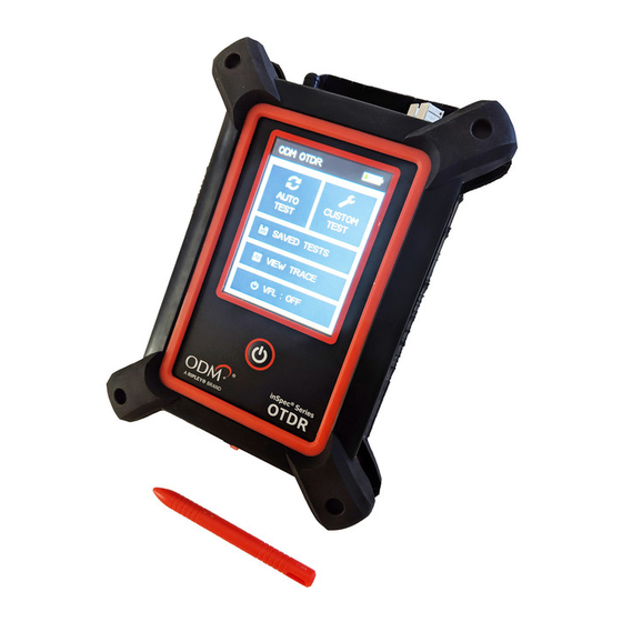
Chapter 6: OTR 800 Description OTDR Physical Description Instrument Enclosure The ODM® Brand OTDR 800 is packaged in a rugged housing and further protected by a rubberized boot. Although the front panel is weather-resistant, care must be taken to prevent liquids and contaminants from damaging the fragile optical and electrical connectors, as well as the glass display. -
Page 6: Battery Replacement
Battery Replacement The battery is not field-replaceable. Contact the factory to acquire an RMA and return the unit to the factory for battery replacement. The Li-ion battery pack should not be punctured, incinerated, or disposed of improperly. WARNING To Prevent Fire or Shock Hazard: •... -
Page 7: Chapter 8: Otdr Operation
Chapter 8: OTDR Operation Entering OTDR Function Press the Power button to turn on the OTDR 800. The unit has two OTDR options to choose for running a network test: Auto Test and Custom Test. Select either option to begin entering test parameters. WARNING Before connecting a fiber to the OTDR, ensure that the fiber has no active optical sources or instruments connected at the other end. - Page 8 The Active Configuration shows and uses the parameters used in CUSTOM TEST the most recent test. The parameters may be identical to one of the Test Configurations other custom test configurations, or saved from running an Auto User Config 1 Edit Configuration Test.
- Page 9 Set Range To set the Range, tap the textbox on the display to open the available range list and choose the desired range for the test. Only one range can be selected for testing. NOTE When setting the Range and Pulse Width, it is necessary to keep in mind that using certain pulse widths with some ranges is not beneficial.
-
Page 10: Otdr Screens
NOTE To obtain reliable, consistent measurements, the user should be aware of the Index of Refraction of the fiber. The proper Index of Refraction (IOR) will maximize the distance measurement accuracy. The IOR is proportional to the speed of light in glass compared to the speed of light in a vacuum, and can be calculated using the equation IOR = C (the speed of light in a vacuum) / V (the speed of light in fiber). -
Page 11: Menu Icon Definitions
Menu Icon Definitions The menu bar is found at the top of every OTDR results screen. Below is the list of icon buttons and their meaning. Brings the user back to the home screen. HOME Saves the Current Trace Data. The User can Name the File and Select the Project to SAVE Save to. -
Page 12: Event Table View
Event Table View VIEW SELECTED Navigation Arrows Zoom View Selected Event in Trace View Event Table Loss Between Event Loss Event Previous and in dB Location dB per Km, Kf or Mi Current Events Pass/Fail Between Events Event Number EOF Event Information System Link... -
Page 13: Event Analysis
LOSS: Event Loss is the loss of the splice, mated pair, or other effect on the fiber considered to be an event. A positive number is the amount of loss and a negative number indicates a gain normally due to mismatched index of refraction. It is a configurable threshold for Pass/Fail purposes. - Page 14 Trace View Description Unit of Measure The Distance Unit of Measurement is available in Kilometer (Km), Kilo feet (Kf) or Miles (Mi). To set the Unit of Measurement, change the unit in the test parameters. Zoom There are six Zoom Levels: 1x, 2x, 4x, 8x, 16x and 32x. To change the Zoom Level, tap the Zoom button on the screen. It will cycle through the six levels.
-
Page 15: Loss Measurement Settings
When using this 2-Point Loss Mode, it is necessary to set the cursors and loss areas in clear backscatter (areas that do not consist of other events). For accurate loss measurements, set a cursor at the beginning of an event and set the loss measurement areas. Loss Measurement Areas follow the undulations of the backscatter line unlike 4-Point areas. -
Page 16: Chapter 9: Project Management
Project Management Screen ODM OTDR Projects OTDR Project Folder List Factory AUTO CUSTOM TEST TEST Selected Project Navigation Arrows RIPLEY [DEFAULT] VIEW TRACE Delete Selected Project Rename Selected Project VFL : OFF Return to Home Back Edit Screen Create New Project Fig 9.1... -
Page 17: Project Management Operation
[Default], therefore, any files saved without creating a new project will be save to the [Default] folder. When the unit is turned off, the previously selected folder will remain as the active folder. File Management Screen Projects Files - RIPLEY OTDR Trace Files List Factory... -
Page 18: File Management Operation
File Management File Menu Tap the arrow to the right of the highlighted project name. If the project is not highlighted, use the navigation arrows to select it. Alternatively, tap on the project name itself to select it. 10.2 File management Operation Open/View a Trace To open a trace, use the navigation arrows to highlight the appropriate trace and tap the arrow to the right of the file name. -
Page 19: Vfl Specifications
LASER SAFETY CLASS 1 SAFETY PER FDA/ CDRH AND IEC-825-1 REG. Ripley Tools reserves the right to change specifications without notice. 11.2 VFL Specifications EMITTER TYPE Laser Photo Diode 1100 - 1700 nm InGaAs -70 to +9 dBm with Interchangeable FC Adapter WAVELENGTH 650 nm ±... - Page 20 QA groups of major wireless carriers. Ripley Tools will only issue replacement certificates to the company or individual who initially paid for the training course. Contact Ripley Tools to receive more information or to set up a certification course. RIPLEY TOOLS...
Need help?
Do you have a question about the ODM OTDR 800 and is the answer not in the manual?
Questions and answers