Advertisement
Quick Links
MicroMod ESP32 Processor Board Hookup Guide
Introduction
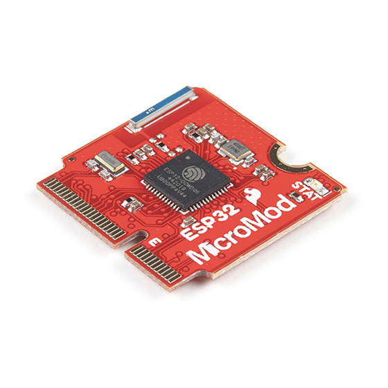
Introducing the SparkFun MicroMod ESP32 Processor Board! This bad boy pops an M.2 connector onto the
ESP32 so you can take advantage of all that lovely ESP32 power with any of our MicroMod carrier boards. Grab
yourself an ESP32 MicroMod Processor Board and let's dive in!
SparkFun MicroMod ESP32 Processor
WRL-16781
Product Showcase: SparkFun MicroMod Ecosystem
Product Showcase: SparkFun MicroMod Ecosystem
Advertisement

Related Manuals for sparkfun MicroMod ESP32


Summary of Contents for sparkfun MicroMod ESP32
- Page 1 MicroMod ESP32 Processor Board Hookup Guide Introduction Introducing the SparkFun MicroMod ESP32 Processor Board! This bad boy pops an M.2 connector onto the ESP32 so you can take advantage of all that lovely ESP32 power with any of our MicroMod carrier boards. Grab...
- Page 2 SparkFun MicroMod ATP Carrier Board Board DEV-16885 DEV-16400 SparkFun MicroMod Input and Display Carrier Board DEV-16985 You'll also need a USB-C cable to connect the Carrier to your computer and if you want to add some Qwiic breakouts to your MicroMod project you'll want at least one Qwiic cable to connect it all together.
- Page 3 Suggested Reading The SparkFun MicroMod ecosystem is a unique way to allow users to customize their project to their needs. Do you want to send your weather data via a wireless signal (eg. Bluetooth or WiFi)? There's a MicroMod processor for that.
-
Page 4: Hardware Overview
A short Hookup Guide to get started with the SparkFun MicroMod Input and Display Carrier Board Hardware Overview In this section we'll cover what's included on the MicroMod ESP32 Processor Board. M.2 Connector All of our MicroMod Processor boards come equipped with the M.2 MicroMod Connector, which leverages the M.2 standard and specification to allow you to install your MicroMod Processor board on your choice of carrier... - Page 5 520kB internal SRAM Integrated 802.11 B/G/N WiFi transceiver Integrated dual-mode Bluetooth (classic and BLE) 2.7 to 3.6V operating range 500µA sleep current under hibernation 10-electrode capacitive touch support Hardware accelerated encryption (AES, SHA2, ECC, RSA-4096) 16MB Flash Storage Stat LED Wireless Antenna Need wireless? The Espressif chip provides built-in BLE as well as a WiFi transceiver which sends and receives data through a 2.4GHz Antenna.
- Page 6 PinOut Notes The ESP32 MicroMod has a few quirks. The ESP32's GPIO pins provide a lot of flexibility with what each pin can be used for. Whether it's I C, I S, SPI, UART, or PWM, the ESP32 MicroMod can do just about everything! However, with that flexibility and a fixed number of GPIO pins, the ESP32 isn't able to do it all at the same time.
- Page 7 If driven low, the boot messages printed by the ROM bootloader (at 115200 baud) are silenced. If unconnected or driven high, the messages will be printed as they normally are. On the ESP32 MicroMod Processor, this pin is connected to G0. We love us some I C! We've broken out two I C buses, which can be used with our Qwiic system.
- Page 8 #CS - This is the chip select pin, which is connected to GPIO 5, or MicroMod pad 55. Note: You may not recognize the COPI/CIPO labels for SPI pins. SparkFun is working to move away from using MISO/MOSI to describe signals between the controller and the peripheral. Check out this page for more on our reasoning behind this change.
- Page 9 SPI_SCK AUD_OUT SPI_CS# AUD_IN SCL1 AUD_LRCLK AUD_LRCLK SCL1 SDA1 AUD_BCLK AUD_BCLK SDA1 BATT_VIN3 AUD_IN PWM1 AUD_OUT AUD_BCLK SDA1 AUD_LRCLK SCL1 PWM0 AUD_IN CAM_TRIG AUD_OUT Interrupt BOOT USB_VIN RESET USB_D- USB_D+ 3.3V Board Dimensions...
-
Page 10: Hardware Hookup
To get started with the ESP32 Processor Board, you'll need a carrier board. Here we are using the MicroMod Input and Display Carrier Board. Align the top key of the MicroMod ESP32 Processor Board to the screw terminal of the Input and Display Carrier Board and angle the board into the socket. - Page 11 Once the board is in the socket, gently hold the MicroMod Processor Board down and tighten the screw with a Phillip's head. Once the board is secure, your assembled MicroMod system should look similar to the image below! Connecting Everything Up With your processor inserted and secured it's time to connect your carrier board to your computer using the USB-C connector on the Carrier.
- Page 12 Arduino library, please check out our installation guide. To get started with the MicroMod ESP32 Processor Board, you'll need to install the ESP32 Board Definition. Open the Arduino IDE (must be v1.8.13 or later) and navigate to File->Preferences, like so: Having a hard time seeing? Click the image for a closer look.
- Page 13 Having a hard time seeing? Click the image for a closer look. Search for "ESP32", and you should find the SparkFun ESP32 Boards board package. Make sure the latest version is selected and click Install. Having a hard time seeing? Click the image for a closer look.
- Page 14 Having a hard time seeing? Click the image for a closer look. Then select your serial port under the Tools > Port menu. Having a hard time seeing? Click the image for a closer look. You can also select the Upload Speed: "921600" baud -- the fastest selectable rate -- will get the code loaded onto your ESP32 the fastest, but may fail to upload once-in-a-while.
- Page 15 With everything setup correctly, upload the code! Once the code finishes transferring, open the serial monitor and set the baud rate to 115200. You should see 's begin to fly by. You may also notice that when Hello, world! the ESP32 boots up it prints out a long sequence of debug messages. These are emitted every time the chip resets -- always at 115200 baud.
- Page 16 #include <WiFi.h> // WiFi network name and password: const char * networkName = "YOUR_NETWORK_HERE"; const char * networkPswd = "YOUR_PASSWORD_HERE"; // Internet domain to request from: const char * hostDomain = "example.com"; const int hostPort = 80; const int BUTTON_PIN = 0; const int LED_PIN = LED_BUILTIN;...
- Page 17 digitalWrite(LED_PIN, ledState); ledState = (ledState + 1) % 2; // Flip ledState delay(500); Serial.print("."); Serial.println(); Serial.println("WiFi connected!"); Serial.print("IP address: "); Serial.println(WiFi.localIP()); void requestURL(const char * host, uint8_t port) printLine(); Serial.println("Connecting to domain: " + String(host)); // Use WiFiClient class to create TCP connections WiFiClient client;...
- Page 18 void printLine() Serial.println(); for (int i=0; i<30; i++) Serial.print("-"); Serial.println(); Make sure you fill in the variables with the name (or SSID) and password of your networkName networkPswd WiFi network! Once you've done that and uploaded the code, open your serial monitor. Having a hard time seeing? Click the image for a closer look.
- Page 19 Based on Neil Kolban example for IDF: https://github.com/nkolban/esp32-snippets/blob/master/ cpp_utils/tests/BLE%20Tests/SampleWrite.cpp Ported to Arduino ESP32 by Evandro Copercini #include <BLEDevice.h> #include <BLEUtils.h> #include <BLEServer.h> // See the following for generating UUIDs: // https://www.uuidgenerator.net/ #define SERVICE_UUID "4fafc201-1fb5-459e-8fcc-c5c9c331914b" #define CHARACTERISTIC_UUID "beb5483e-36e1-4688-b7f5-ea07361b26a8" class MyCallbacks: public BLECharacteristicCallbacks { void onWrite(BLECharacteristic *pCharacteristic) { std::string value = pCharacteristic->getValue();...
- Page 20 pCharacteristic->setCallbacks(new MyCallbacks()); pCharacteristic->setValue("Hello World"); pService->start(); BLEAdvertising *pAdvertising = pServer->getAdvertising(); pAdvertising->start(); void loop() { // put your main code here, to run repeatedly: delay(2000); Once you have uploaded your code, open the serial monitor set at 115200 baud so you can see the message that we will write.
- Page 21 The next page will show you communications and options for doing so. Select Write,Read.
- Page 22 Finally, we can choose the option that allows us to write a message. Select Write Value.
- Page 23 Now we can write our message. Make sure you choose Text, write yourself a message, and click the Write button.
-
Page 24: Further Examples
You'll notice that in this tutorial, we've selected the Input and Display Carrier Board, but have focused our examples on the Esp32 Processor Board. If you're interested in examples specifically for our carrier board, head on over to our SparkFun MicroMod Input and Display Carrier Board Hookup Guide. -
Page 25: Troubleshooting
SparkFun Technical Assistance page for some initial troubleshooting. If you don't find what you need there, the SparkFun Forums are a great place to find and ask for help. If this is your first visit, you'll need to create a Forum Account to search product forums and post questions. - Page 26 SparkFun MicroMod Forums Resources and Going Further For more information about the MicroMod ESP32 Processor Board, check out the following links: Schematic (PDF) Eagle Files (ZIP) Board Dimensions (PNG) ESP32 Datasheet (PDF) GitHub Hardware Repo For more information about the SparkFun MicroMod Ecosystem, take a look at the links below:...
Need help?
Do you have a question about the MicroMod ESP32 and is the answer not in the manual?
Questions and answers