Table of Contents
Advertisement
Quick Links
Page 1 of 19
RFM69HCW Hookup Guide
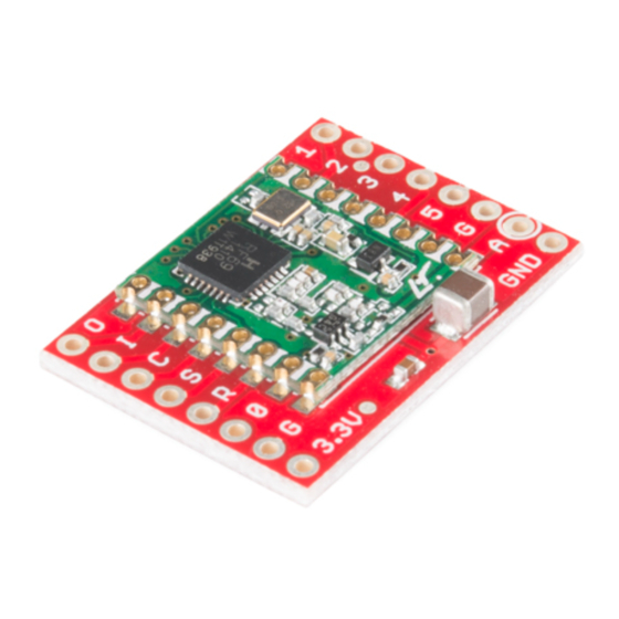
Introducing the RFM69
The RFM69HCW is an inexpensive and versatile radio module. You can
use it to send text or binary data between two or hundreds of modules. It's
perfect for building inexpensive short-range wireless networks for home
automation, citizen science, and more.
The RFM69HCW comes in two flavors of frequency, the 915 MHz version
and the 434 MHz version.
Interface and Example Code
The RFM69HCW can't do anything by itself; it needs to be connected to a
microcontroller such as an Arduino. The RFM69HCW uses a four-wire
Synchronous Peripheral Interface (SPI) plus an interrupt line. Most
microcontrollers, including the Arduino, offer an SPI interface.
Felix Rusu of LowPowerLab has written an excellent Arduino library for the
RFM69 that handles the details of setting up the module and sending and
receiving data. This guide will cover interfacing the RFM69HCW to an
Arduino microcontroller using this library.
If you're using a different microcontroller, the information here plus the
datasheet and the library source code should help get you up and running.
(If you write example code for another system, we'll be glad to add it to the
code repository).
Required Materials
In this tutorial we'll show you how to get two modules talking to each other,
but keep in mind that you can use more than two modules in your projects.
Here's what you'll need:
• Two RFM69HCW modules (with matching frequencies):
◦ 915 MHz (WRL-12775)
or
Advertisement
Table of Contents

Subscribe to Our Youtube Channel
Related Manuals for sparkfun RFM69HCW


Summary of Contents for sparkfun RFM69HCW
- Page 1 434 MHz version. Interface and Example Code The RFM69HCW can’t do anything by itself; it needs to be connected to a microcontroller such as an Arduino. The RFM69HCW uses a four-wire Synchronous Peripheral Interface (SPI) plus an interrupt line. Most microcontrollers, including the Arduino, offer an SPI interface.
-
Page 2: Suggested Reading
Suggested Reading We recommend you be familiar with the following topics before working with the RFM69HCW. If you’d like to brush up on any of these things, follow the links and come back when you’re done. • How to Solder •... - Page 3 Indoors we’ve seen it work for over 50 meters through multiple walls. The RFM69HCW is capable of transmitting at up to 100 mW and up to 300 kb/s, but you can change both of those values to fit your application. For example, you can maximize range by increasing the transmit power and reducing the data rate.
-
Page 4: Power Requirements
RFM69HCW datasheet for more information. Power requirements The RFM69HCW will run on voltages from 1.8V to 3.6V, and can draw up to 130mA of current when it’s transmitting. IMPORTANT! Do not power your RFM69 with 5V or connect the data lines directly to a 5V microprocessor. -
Page 5: Hardware Connections
Step 1: Solder male header onto the RFM69HCW: Break off one 8-pin length of Male Breakaway Header, and solder it to the “O I C S R 0 G 3.3V” side of the RFM69HCW board. You can solder it to the top or bottom, your choice. -
Page 6: Wiring Diagrams
A 3.3V Arduino Pro Mini is also a great choice, since both boards are very small: 5V Arduinos You can connect the RFM69HCW to a 5V Arduino, such as our RedBoard, if you use a logic level translator between them. The translator translates the Arduino’s 5V signals to 3.3V signals, which won’t damage the... - Page 7 (D13) is also used by the SPI port’s SCK line. We use the SPI port to communicate with the RFM69HCW, so this LED will be on a lot of the time. To make up for this, the example code is written so you can stick any old LED into your Arduino, with the long (positive) lead in D9, and the short (negative) lead in D8.
-
Page 8: Antenna Placement
Add a Dipole Antennas love to have a ground underneath them. The RFM69HCW board contains a ground, but, the larger the ground, the better. A dipole is an antenna that has an equal length of grounded wire extending below the board. - Page 9 Page 9 of 19 To make a dipole, cut a second wire the same length as your antenna, solder it to one of the “G” / “GND” header holes adjacent to the antenna, and point it in the opposite direction of the antenna (straight down instead of up).
-
Page 10: How It Works
-Monty Python and the Holy Grail The information below will help you better understand how your RFM69HCW module works, which will help you use it more effectively in your projects. However, if you’re itching to start using it right away, you can jump straight to Running the Example Code. -
Page 11: Network Number
You get to (and must!) choose these numbers. Even if you just have two nodes, you’ll need to give them address numbers in your code. The address is set by your code each time the RFM69HCW is powered up; it doesn’t remember the address when it is powered off. - Page 12 Felix Rusu of LowPowerLab has written an excellent Arduino library for the RFM69 that handles the details of setting up the module and sending and receiving data. This guide will cover interfacing the RFM69HCW to an Arduino microcontroller using this library.
- Page 13 Note that the author of the library keeps the most up-to-date version at github.com/LowPowerLab/RFM69. SparkFun has created their own repository for the RFM69HCW Breakout Board that includes a copy of this library plus hardware schematics, example code, etc. at github.com/sparkfun/RFM69HCW_Breakout.
- Page 14 4. Below these lines will be a section for defining the radio frequency of your RFM69HCW board. Uncomment the line corresponding to your board’s frequency, and make sure the others are commented (have // in front of them.
- Page 15 Page 15 of 19 // RFM69HCW Example Sketch // Send serial input characters from one RFM69 node to another // Based on RFM69 library sample code by Felix Rusu // http://LowPowerLab.com/contact // Modified for RFM69HCW by Mike Grusin, 4/16 // This sketch will show you the basics of using an // RFM69HCW radio module. SparkFun's part numbers are: // 915MHz: https://www.sparkfun.com/products/12775 // 434MHz: https://www.sparkfun.com/products/12823 // See the hookup guide for wiring instructions: // https://learn.sparkfun.com/tutorials/rfm69hcwhookupguide // Uses the RFM69 library by Felix Rusu, LowPowerLab.com // Original library: https://www.github.com/lowpowerlab/rfm69 // SparkFun repository: https://github.com/sparkfun/RFM69HCW_B reakout // Include the RFM69 and SPI libraries: #include <RFM69.h> #include <SPI.h> // Addresses for this node. CHANGE THESE FOR EACH NODE! #define NETWORKID 0 // Must be the same for all nodes #define MYNODEID 1 // My node ID #define TONODEID 2 // Destination node ID // RFM69 frequency, uncomment the frequency of your module: //#define FREQUENCY RF69_433MHZ #define FREQUENCY RF69_915MHZ // AES encryption (or not): #define ENCRYPT true // Set to "true" to use encryption #define ENCRYPTKEY "TOPSECRETPASSWRD" // Use the same 16by te key on all nodes // Use ACKnowledge when sending messages (or not): #define USEACK true // Request ACKs or not // Packet sent/received indicator LED (optional): #define LED 9 // LED positive pin #define GND 8 // LED ground pin // Create a library object for our RFM69HCW module: RFM69 radio; ...
- Page 16 Page 16 of 19 // Set up the indicator LED (optional): pinMode(LED,OUTPUT); digitalWrite(LED,LOW); pinMode(GND,OUTPUT); digitalWrite(GND,LOW); // Initialize the RFM69HCW: radio.initialize(FREQUENCY, MYNODEID, NETWORKID); radio.setHighPower(); // Always use this for RFM69HCW // Turn on encryption if desired: if (ENCRYPT) radio.encrypt(ENCRYPTKEY); } void loop() { // Set up a "buffer" for characters that we'll send: static char sendbuffer[62]; static int sendlength = 0; // SENDING // In this section, we'll gather serial characters and // send them to the other node if we (1) get a carriage retu // or (2) the buffer is full (61 characters). // If there is any serial input, add it to the buffer: if (Serial.available() > 0) { char input = Serial.read();...
- Page 17 (radio.sendWithRetry(TONODEID, sendbuffer, sendleng th)) Serial.println("ACK received!"); else Serial.println("no ACK received"); } // If you don't need acknowledgements, just use send(): else // don't use ACK { radio.send(TONODEID, sendbuffer, sendlength); } sendlength = 0; // reset the packet Blink(LED,10); } } // RECEIVING // In this section, we'll check with the RFM69HCW to see // if it has received any packets: if (radio.receiveDone()) // Got one! { // Print out the information: Serial.print("received from node "); Serial.print(radio.SENDERID, DEC); Serial.print(", message ["); // The actual message is contained in the DATA array, // and is DATALEN bytes in size: for (byte i = 0; i < radio.DATALEN; i++) Serial.print((char)radio.DATA[i]); // RSSI is the "Receive Signal Strength Indicator", // smaller numbers mean higher power. Serial.print("], RSSI "); Serial.println(radio.RSSI); // Send an ACK if requested.
-
Page 18: Signal Strength
Page 18 of 19 Running the Sketches You now have two nodes that will send messages to each other, but, to use them, we’ll need to open two serial terminals. One way to do this is to run two separate Arduino IDEs. You’ll have to actually start Arduino twice - you can’t just open a “new”... - Page 19 • RFM69HCW GitHub Repository • RFM69HCW Schematic • RFM69HCW Eagle Files • RFM69HCW Datasheet For more wireless fun, check out these other great SparkFun tutorials: GPS Shield Hookup Guide XBee WiFi Hookup Guide This tutorial shows how to get An overview of Digi's WiFi XBees,...
Need help?
Do you have a question about the RFM69HCW and is the answer not in the manual?
Questions and answers