
Related Manuals for Pompetravaini TRVK Series


Summary of Contents for Pompetravaini TRVK Series
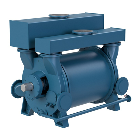
- Page 1 (NA4.IS.VUOC.IN00 -- Rev. 3.8_11-2020) OPERATING MANUAL LIQUID RING VACUUM PUMPS TRVK - TRSK...
-
Page 2: Warranty
For pumps subjected to the ATEX 94/9/CE directive it is available a dedicated integrative manual. According to what expected from 2012/19/UE Directive on Waste Electric and Electronic Equipment the electrical pump assembly from us supplied (pump coupled with an electrical motor of Pompetravaini supply or customer supply) placed on the market after the 15 of August 2018 fell within the limits of application of the Directive. - Page 3 INDEX 9.4 - Pump engineering data 1 - General instructions General instruction 10 - Check list prior to start-up Reading template 11 - Starting, operating and stopping procedures 2 - Safety instructions 11.1 - Start-up 11.2 - Operation 3 - In case of emergency 11.3 - Shut down 3.1 - Basic first aid 12 -...
-
Page 4: General Instructions
Directive and ATEX Directive if requested). The appearance and arrangement of the markings on the nameplate may differ depending on the type of pump and the recipient of the pump. Or for some branches of Pompetravaini customized executions are provided. The minimum information required by the regulations remains present in the various possible configurations. - Page 5 Pompetravaini nameplate shows: Name of the manufacturer and address: Pompetravaini spa Pump type, es.: Centrifugal pump- Pompa centrifuga Model, es.: TCH 40-125/1-R/A3 Serial number es.: HG533 Year (of production), es.: 2020 Number of Item (of the customer), es.: 459.25 Turn by minute/rpm, es.: 2900 Weight, kg, es.:...
- Page 6 The Service Card bears all the information of the pump nameplate and still others more as complement. For the management system of Pompetravaini, starting with the serial number of the pump or vacuum system it is possible to uniquely identify the product code and its bill of material.
-
Page 7: Safety Instructions
2 - SAFETY INSTRUCTIONS CAUTION: CAREFULLY READ FOLLOWING INSTRUCTIONS. STRICTLY ADHERE TO THE INSTRUCTIONS LISTED BELOW TO PREVENT PERSONAL INJURIES AND/OR EQUIPMENT DAMAGE. ALWAYS apply the pump for the conditions outlined on the confirming order. Electrical connections on the motor or accessories must ALWAYS be carried out by authorised personnel and in accordance to the local codes. - Page 8 HYDROSYS which utilise said pumps. NOTE: Capacities, vacuum and pressures are nominal and are the maximum attainable values under standard operating conditions. Please contact POMPETRAVAINI for data on liquid ring compressors series TR… Single stage liquid ring vacuum pumps TRVK...
- Page 9 POMPETRAVAINI's customer service department.
- Page 10 Fig. 2 Fig. 1 ----------------------------------------------------------------------------------------------------------------------------- -------------------------------- Fig. 3 >90 Fig. 4 Operating manual liquid ring vacuum pumps TRVK - TRSK...
-
Page 11: Storage Instructions
Coupling sizes and permissible coupling tolerances listed in this manual are applicable to the particular coupling brand installed by POMPETRAVAINI as a standard. For sizes and tolerances of other type of couplings, follow the instructions given by their respective manufacturer. - Page 12 Should the pump operate at high temperatures that could upset the coupling alignment, it is necessary to check the alignment to secure proper working operation at such operating temperatures. It is recommended the use of proper hand protections such as gloves, when carrying out the operations listed below (schematics for various assemblies are shown).
- Page 13 6 - Rotate back the coupling guard by hand through the two openings of the lantern so that both openings are completely covered. This will complete the alignment verification of the MONOBLOCK design. 7 - Remove the coupling guard and its extension (if there is one) attached to the pump, by removing the two locking screws (see fig.
- Page 14 NOTE: During the first period of operation, it may be noted the presence of dust due to settling wear of the belts, this is a normal phenomena. For more information consult Pompetravaini. RIFERIMENTI STAMPED STAMPATI...
-
Page 15: Electrical Connections
8 - ELECTRICAL CONNECTIONS Electrical connections must be made exclusively by qualified personnel in accordance with the instructions from the manufacturer of the motor or other electrical components and must adhere to the local National Electrical Code. FOLLOW ALL SAFETY PRECAUTIONS AS LISTED IN CHAPTER 2. BEFORE DOING ANY WORK TO THE INSTALLATION DISCONNECT ALL POWER SUPPLIES. -
Page 16: Piping Connections
9.1 - PIPING CONNECTIONS Identify first locations and dimensions of all connections required to interconnect the pump with the installation, then proceed with the actual piping: connect the pump suction and discharge flanges, the service liquid line and all other service connections (packing box flushing, drainage, etc.) BE SURE TO PIPE THE CORRECT CONNECTION FROM THE INSTALLATION TO THE RESPECTIVE PUMP CONNECTION ! - Page 17 9.3 - INSTALLATION SCHEMATICS FOR LIQUID RING VACUUM PUMPS The working principle of the vacuum pump requires a continuous flow of fresh and clean liquid that enters the pump at the service liquid connection identified by the letter “Z” (see following chapter). The liquid is discharged together with the handled gas through the pump discharge flange.
-
Page 18: Pump Model
A heat exchanger is required to lower and control the temperature of the recycled service liquid: for sizing and calculations of heat loads consult Pompetravaini. A circulating pump will be required for those applications where the vacuum pump operates for... -
Page 19: Check List Prior To Start-Up
Open valve at gas discharge if installed and partially open the valve at the suction side. When pump is fitted in a partial recovery or total recovery or HYDROSYS systems, as built by POMPETRAVAINI, it is required to have drain valve at separator in the closed position, flow regulating valve and overflow valve in the open positions. -
Page 20: Operation
NOTE: HYDROSYS systems engineered with multiple pumps are fitted with isolating valves at suction, discharge, and service liquid lines of each pump. When one or more pumps are not operating it is required to isolate the idle pump(s) by closing these valves. When the pumps are put back into service the said valves (at suction and discharge) must be opened. - Page 21 The flow of service water at 15°C, for standard pumps and normal operating conditions at various vacuum levels, is listed on the specific pump curves. Usually the temperature rise of service water, when handling dry air at 20 ° C, is approximately 4 to 8°C. When condensable (e.g.: vapours) are present in the gas stream the heat load to be removed by the service water will be higher, therefore the service water temperature rise will be higher.
-
Page 22: Mechanical Seals
ATT.: Take particular care of possible mechanical seals leaks of the pumped medium that, due to its characteristics, might be dangerous for the environment. N.B.: The data provided refers to the pumps of standard construction. For special constructions contact Pompetravaini. 13.3 - PACKED STUFFING BOXES Pumps fitted with packed stuffing boxes require packing flushing either from an external source or directly from the pumped media through pump internal passages. - Page 23 Fig. 23 Fig. 24 External flushing to the packing Internal flushing to the packing 13.3.1 - ADJUSTMENT OF THE PACKING All adjustment operations must be performed with the PUMP STOPPED following the safety measures given in chapter 2. After completion of the work ALWAYS re-install the safety guards previously removed. At first start up loosen the nuts of the packing gland allowing a steady flow of liquid to drain out (see fig.
-
Page 24: Trouble Shooting: Problems, Causes And Solutions
14 - TROUBLE SHOOTING: PROBLEMS, CAUSES AND SOLUTIONS Consult the following tab. 4 when problems are experienced, if solutions are not found in this chart or should there be any doubts, do not hesitate to contact POMPETRAVAINI or your local representative. Tab. 4 - LIST OF PROBLEMS... -
Page 25: Spare Parts
We recommend the use of original spares: in case this is not respected, POMPETRAVAINI declines any responsibility for eventual damages and not correct running caused by not original spare parts. -
Page 26: Engineering Data
Regarding the performance variation due to changes of specific gravity and viscosity, it can be assumed a proportional variation in power consumption however, the changes in capacity at different pressures must be analysed case by case. Please refer the conditions to POMPETRAVAINI when these corrections are needed. ABSOLUTE PRESSURE... -
Page 27: Unit Conversion Table
17.3 - UNIT CONVERSION TABLE Absolute pressure Vacuum Operating manual liquid ring vacuum pumps TRVK - TRSK... - Page 28 (blank page) Operating manual liquid ring vacuum pumps TRVK - TRSK...
- Page 29 (blank page) Operating manual liquid ring vacuum pumps TRVK - TRSK...
- Page 30 (blank page) Operating manual liquid ring vacuum pumps TRVK - TRSK...
- Page 31 20022 CASTANO PRIMO (Milano) ITALY - Via per Turbigo, 44 – Zona Industriale Tel. 0331 889000 – Fax 0331 889090 - www.pompetravaini.com firmataria della presente, dichiara sotto la propria esclusiva responsabilità, che la macchina è conforme a quanto prescritto dalle Direttive...
- Page 32 PRINTED IN ITALY Continuing research of POMPETRAVAINI results in product improvements: therefore any specification may subject to change without notice. S.p.A. 20022 CASTANO PRIMO (Milano) ITALY Via per Turbigo, 44 – Zona Industriale Tel. 0331 889000 – Fax 0331 889090 www.pompetravaini.com...
Need help?
Do you have a question about the TRVK Series and is the answer not in the manual?
Questions and answers