Table of Contents
Advertisement
Advertisement
Table of Contents

Related Manuals for Pompetravaini BORA FP 243


Summary of Contents for Pompetravaini BORA FP 243
- Page 1 (Rev. 1.3_01-2018) ® HIGH VACUUM PUMPS, EXHAUSTERS AND BLOWERS OPERATING MANUAL...
- Page 2 Failure to strictly adhere to the instructions and recommendations listed in this manual will void the manufacturer’s warranty. Guarantee will be preserved only if the pump maintenance is carried out by Pompetravaini or an authorized service. Any modification introduced to the pump without the authorization of Pompetravaini will lead to the loss of the guarantee.
-
Page 3: Table Of Contents
INDEX INTRODUCTION REPLACEMENT OF THE 1ST SUPPLY OIL OF SEAL 7.2.3.1 SHAFT GENERAL INFORMATION MANUFACTURER’S INFORMATION 7.2.4 CLEANING THE FAN MOTOR PROTECTION GENERAL EXTERNAL CLEANING OF PUMP 7.2.5 METHOD OF CONSULTATION 7.2.6 CHECK OF THE TRANSMISSION ELASTIC ELEMENT PERSONNEL QUALIFICATIONS PERSONAL PROTECTION EQUIPMENT 7.2.7 REPLACEMENT OF THE GEAR AND BEARING OIL... -
Page 4: General Information
The Supplier reserves the right to modify components and/or parts in order to improve or for any other reason, without updating this manual if operation and safety of the pump are not changed. 1.2 - SUPPLIER INFORMATION Pompetravaini S.p.A. Divisione BORA Via per Turbigo, 44 - Zona Industriale... - Page 5 1.4 - PERSONNEL QUALIFICATIONS To ensure that all operations performed on the pump are carried out safely, operators must have the qualifications and requirements to carry out its operations. Operators are classified as follows: FIRST LEVEL OPERATOR: Unqualified personnel, having no specific skills, able to perform simple tasks only. MECHANICAL MAINTENANCE OPERATOR: Technician qualified to work on mechanical parts to carry out any necessary adjustments, maintenance or repairs.
- Page 6 ALWAYS make sure that the pump is permanently fixed and steady to the installation (i.e. during removal, handling, installation, etc.). Pompetravaini-Bora srl disclaims any liability for damage to persons or property resulting from improper use of the pump from tampering with its safety apparatus or failure to observe operational safety standards.
- Page 7 Danger of Entangling There is a permanent impending danger of entangling or entrapping hair and clothing in the cooler fan inside the protection itself near the fan cover casing on the electric motor. Tie long hair up and do not wear baggy clothing, long laces or other items that could get caught up..
-
Page 8: Basic First Aid 9
The pump is near protected electrical connections but where accidental contact can cause electric shock and death. Pompetravaini - BORA disclaims any liability for damage to persons or property due to non-compliance with instructions indicated in pictograms or their improper preservation. -
Page 9: High Vacuum Pumps, Booster Hv
The applications must remain within the limits of permissible suction temperature from 12 to 40 ° C. Pompetravaini- BORA can provide vacuum systems composed by a vacuum volumetric pump in combination with a liquid ring vacuum pump with Hydrotwin system series. -
Page 10: Noise Emissions
The actual sound emission while operating depends, however, on the installation conditions, position and the operating pressure that can be upper than 85 Db(A). If required, appropriate solutions can be supplied by Pompetravaini in order to comply with the legislative provisions in force in the Country of use of the user system. Otherwise, the user must take any appropriate devices for the reduction of the noise level. - Page 11 The pump can be lifted and handled using a fork-lift truck and hoisting means (e.g. ropes, hooks, etc.) suitably sized for its weight (indicated in the technical data table and on the rating plate) and applied as indicated in the following diagram to obtain the best harness in terms of safety and center of gravity.
-
Page 12: Installation
HOISTING PLANT ON BENCH Fig. 5 WARNING In order to transport the pump, we recommend you to prepare it as shown in the following paragraph. 4.4 – STORAGE Shut down the inlet and outlet ports with the specific protections. The pump has to be stored in its packaging and kept in covered, dry, protected places that are not exposed to bright sunlight, with temperatures in the range indicated in point 3.3 of this manual.. -
Page 13: Motor Installation On Blowers And
Fig. 6 Installation with horizontal f/flow Installation with vertical f/flow DANGER Use an intake filter to protect the pump from dust, sand, masonry debris, cutting filaments and threadings, drops and welding dirt and sealant residue produced when connecting the pipes that could damage rotor lobes causing seizure. -
Page 14: Motor Installation On Booster Hv
It is possible to install any type of electric or hydraulic motor that has the features described in the table of technical data, with flange and shaft corresponding to: Tab. 5 BORA HV 73 M90/2 B5 IEC-72, 1.5-2,7 kW 50-60Hz BORA FP 243 M90/2 B5 IEC-72, 1.5-2,7kW 50-60Hz BORA HV 103 M90/2 B5 IEC-72, 2.2-2.7kW 50-60Hz BORA FP 363 M90/2 B5 IEC-72, 2.2-2.7kW 50-60Hz... -
Page 15: Connection
4.9 - CONNECTION DANGER Pump connections should be performed by skilled and trained personnel only. 4.9.1 - INTAKE AND OUTLET CONNECTIONS All the pump’s openings are protected in order to prevent extraneous parts entering it. Only remove these protections positioned on the intake and outlet points shortly before connecting to the user system. Using thick steel hoses reduces the noise. -
Page 16: Electrical Connection
DANGER Lay the pump power cable in such a way that it cannot cause the risk of tripping or falling or can be damaged. Always install an electric protection system between the pump and power supply; the pump’s absorption levels are shown on the electric motor plate. -
Page 17: Accessories
5 – ACCESSORIES 5.1 – RV VACUUM RELIEF VALVE SETTING INSTRUCTIONS The vacuum relief valve is an accessory available for blowers and exhausters in order not to generate an excessive lowering of absolute pressure on suction side. Fit the valve on suction side of the blower/exhauster and prearrange a pressure take-off closed to the suction side of the same. -
Page 18: Soundproofing Booth
5.11 - ANTI ACCIDENT DRIVE COVER If the coupling between the pump and the electric motor is not made by Pompetravaini - Bora, please note that, in all cases a protection must be provided in order to avoid contact with moving parts using a cover conforming to the regulations in force. -
Page 19: Operation
It is possible to use by-pass valves in order to drive short time vacuum cycles: long lasting gas recirculation may cause overheating of the pump. Performances active control through frequency inverter is maximized by POMPETRAVAINI - BORA DVD-2 system that guarantees minimum time to vacuum and safety of the pumps. For more information please contact POMPETRAVAINI - BORA. -
Page 20: Stop
WARNING In order to reducing energy consumption and not damaging the pump, it is advisable not to start up more than 6 times / hour and that they are equally distributed. DANGER The pump working temperature depends on the characteristic of the processed fluid. High temperature levels can be due to room temperature or gas intake that is too high, pressure differential that is greater than that allowed, low or high oil level, installation is in constricted spaces, exposure to direct sun rays, dust deposits on the motor’s cooling fan or on the fan cover casing. -
Page 21: General Warnings
• Use suitable individual protective equipment. If failing to understand fully the information or procedures contained in this chapter, contact Pompetravaini - BORA for clarification before proceeding. Only trained or authorized personnel have the necessary expertise to perform tasks with the skills appropriate for intervention. -
Page 22: Operations Table
7.2 – OPERATIONS TABLE The following table shows all required periodic operations to maintain pump efficiency. DANGER Wear suitable protection equipment when carrying out maintenance work Tab.7 OPERATION TYPE FREQUENCY OPERATOR QUALIFICATION 24 h Check of the lubricant levels Replacement of the 1st supply gear and bearing oil 1 x 500 h Replacement of the 1st supply shaft seal oil (HV/FP series only) 1 x 500 h... - Page 23 WARNINGE Use exclusively the following oils to lubricate the pump bearings: • MOBIL SHC 624. • TEXACO CETUS PAO 46 Change the gear and bearing oil as follows: Disconnect the pump from the mains and bring the work chamber to the atmospheric pressure ...
- Page 24 The machine is originally painted with properly selected paint that allows the highest heat exchange with the air. Even in case of esthetical deterioration we advise to have paint retouches made only in case of a reconditioning performed by Pompetravaini - BORA. WARNING Do not re-paint the compressor in order not to jeopardize the correct heat exchange needed in the heaviest duty use of the machine.
- Page 25 Type and Serial number (you will find these on the identification plate). Pompetravaini - BORA disclaims all responsibility for any deterioration of pump performance or for damages caused due to use of non original spare parts.
- Page 26 Check the motor operation. Replace, if Damaged motor. Qualified technician it is damaged. Check tension V-belts and correct it, if V-belts degraded. necessary. Replace V-belts if they are Qualified technician consumed. Check direction and speed of rotation. Speed of motor rotation is not sufficient. Check the electrical connection and Qualified technician correct it, if necessary.
- Page 27 9.2 – TROUBLE SHOOTING EXHAUSTERS OR AC PROBLEMS LIST OF POSSIBLE CAUSES Vain or scarce performance, insufficient outlet pressure. 1, 2, 3, 4, 5, 6, 7, 8, 9, 10, 11, 12, 17 Excessive performance, outlet pressure higher than expected. 3, 7, 13, 14 High power absorption.
- Page 28 Check that the suction conditions are Intake gas temperature too high. within the established parameters (see Qualified technician 3,1,2). Correct, if necessary. Machine-room has to be appropriately Too high machine-room temperature. ventilated to dissipate the produced Operator heat. If ventilation is deficient, correct it. Cooling air filter clogged.
- Page 29 9.3 – TROUBLE SHOOTING HV e FP SERIES PROBLEMS LIST OF POSSIBLE CAUSES Vain or scarce performance, insufficient outlet pressure. 1, 2, 3, 4, 5, 6, 7, 8, 11, 12, 13, 14, 15, 16, 18, 19, 24 Excessive performance, outlet pressure higher than expected. 3, 7, 20, 21, High power absorption.
- Page 30 Check the rotation speed. Check the electrical Speed of motor rotation is excessive. Qualified technician connection and correct it, if necessary. Drain any excess lubricant, restoring the correct Exceeding quantity of lubricant in the casing Qualified technician level. Check the uniformity of the supporting surface of Deformation caused by foot tightening.
- Page 31 10 – DIMENSIONS AND CHARACTERISTICS Fig. 15 Tab. 10 BORA MODEL 3/8”G 163 HV >200 340÷370 3/8”G 233 HV >300 340÷370 3/8”G 293 HV >300 340÷370 3/8”G 353 HV 1080 >300 340÷370 3/8”G 463 HV 1180 >300 340÷370 3/8”G 673 HV 1140 >300 425÷455...
- Page 32 Fig. 16 Tab. 11 BORA MODEL (max) 3/8”G 243 FP >200 3/8”G 363 FP >200 3/8”G 543 FP >200 BORA MODEL (H7) (JS9) 3” 243 FP Ø130 4XM10 3” 363 FP Ø130 4XM10 3” 543 FP Ø130 4XM10 High vacuum pumps, exhausters and blowers operating manual...
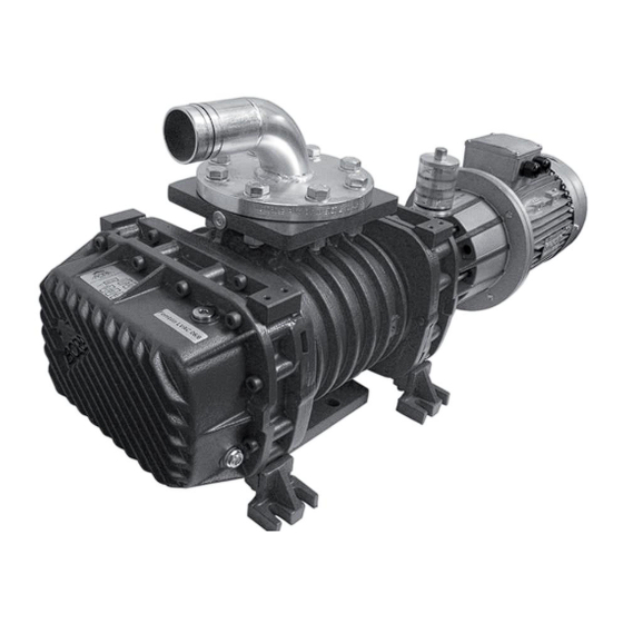
- Page 33 Fig. 17 Tab. 12 Intake Fitting for measuring the intake pressure Outlet Oil viewer of the seal on the shaft Oil sight glass Fixing points Oil filler plug Oil drain plug ( gears and bearings ) Tappo scarico olio (tenuta sull’albero) Motor rating plate Motor fan guard Fitting for measuring the outlet pressure...
- Page 34 Fig. 18 Tab. 14 Pumping Noise level Weight Weight Oil quantity Power BORA ∆P 50 mbar Speed at at 5 mbar( without with quantity shaft model 3000 RPM 5 mbar(A) motor motor drive end seal ∆P 5 mbar l/1’ dB (A) dm 3 dm 3 243 FP...
- Page 35 NOTES PUMP model Serial Number Computer Number Year of manuf....................................LIQUID handled Capacity Suction Pressure Discharge Press. Temperature ..................m ......m ......m ....°C Lethal Toxic Noxious Corrosive Irritant Malodorous ....Clean Dirty With suspended parts Spec. Gravity... Viscosity....
- Page 36 SERVICE LIQUID RECIRCULATION NA5.IS.BORA.GB00 / STAMPATO IN ITALIA Manuale Operativo Pompetravaini- BORA Inglese Continuing research of POMPETRAVAINI results in product improvements: therefore any specifications may be subject to change without notice. POMPETRAVAINI S.p.A. Divisione BORA Via per Turbigo, 44 - Zona Industriale sede operativa: 20022 CASTANO PRIMO - (Milano) –...
Need help?
Do you have a question about the BORA FP 243 and is the answer not in the manual?
Questions and answers