Table of Contents
Advertisement
Quick Links
Advertisement
Table of Contents

Subscribe to Our Youtube Channel
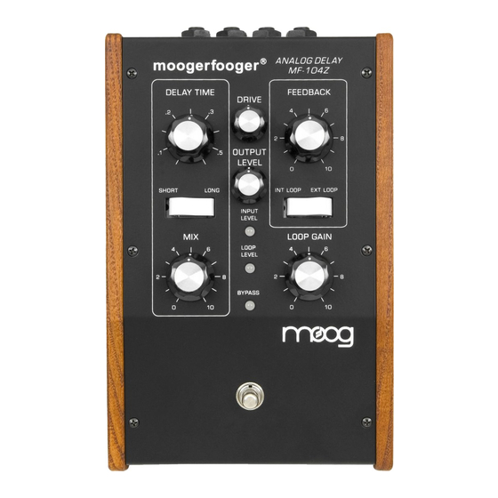
Summary of Contents for Moog Moogerfooger MF 104Z
- Page 4 Please read over all the instructions first and do not attempt this modification unless you feel confident doing so! Moog Music is not responsible for any damages that may occur to your instrument while attempting this mod. Contact Moog Tech Support for assistance (techsupport@moogmusic.com).
- Page 5 At least 32” of 24 gauge wire. (Four 8" lengths of different colored wires recommended) Soldering iron + solder Solder-wick or Pump to remove solder Small DPDT switch (Available from Moog for $14.76. Digikey part # EG2403-ND) Hand drill or drill press with .255” bit A multimeter that can read resistance Disassembly 1.
- Page 6 2. Locate the underside of chip U2 (gently bend the Drive pot back). Cut the traces that connect pins 9 and 11 to pin 10 and attach an 8” wire to pin 10. 3. Jumper pins 9 and 11 of U2 back together with a small bit of wire (approx 1/2”). Measure the resistance between pins 9, 10 and 11.
- Page 7 Note: Different eras of the 104 may have slight component variations. Most notably, you may see two diodes and/or two resistors near the underside of U2. The first picture has the diodes. The second picture has neither. The third has the diodes and resistors. As long as the unit is functioning properly, you need not worry if these components are present or not.
- Page 8 The above picture shows a good length for the switch wiring. Wire the switch as follows 1. Wire U2 pin 16 (+15V) to lug 1. 2. Wire U2 pin 10 to lug 2. 3. Wire 'N' control signal (cathode hole) to lugs 3 & 4. 4.
- Page 9 Drilling Out the Chassis Drilling out the chassis is simple enough if you have experience with a drill. However, it's one of the riskiest parts of the mod. A poorly drilled hole can ruin the chassis! The switch needs to sit between the Int/Ext Loop switch and the wooden side piece.
- Page 10 Testing the Spillover Mod If the mod has been done correctly, the unit should operate normally with the switch in the down position. In Spillover position (switch up) the Mix knob remains active all the time and the delayed signal will not be abruptly cut off when you switch to bypass (red light). With the Feedback knob turned up all the way, the delay signal will last indefinitely, even in bypass mode.
- Page 11 value changes for the different MF-104 versions For both versions Omit D8 and D10 C60 is 820pF C65 is 1200pF R50 is 150K ohm R66 and R67 are 100 ohm For the SD version [570/575 board set] R45 is 7.5K ohm R46 is 22K ohm Daughter board is fully populated Jumper is set 1 and 2...


Need help?
Do you have a question about the Moogerfooger MF 104Z and is the answer not in the manual?
Questions and answers