Table of Contents
Advertisement
Understanding and Using
Your Moogerfooger
®
MF-105B
Bass MuRF
®
TABLE OF CONTENTS
Getting Started............................................3
Frequencies and Filters...............................5
The Bass MuRF's Filters............................7
Envelope Generators.................................10
Sequencers and Pattern Generation.......... 11
The Bass MuRF's Animation................... 11
The Bass MuRF's Tap/Step Input............ 13
Audio Level Controls and Mixing............14
Using Both Outputs Together..................14
Some Typical Setups.................................16
Technical Information...............................17
Limited Warranty......................................19
MF-105B Specifications........................... 20
-The Bass MuRF's Patterns........................22
Appendix B
-The MuRF Pattern Step Adaptor...............27
Advertisement
Table of Contents

Related Manuals for Moog Moogerfooger MF-105B Bass MuRF


Summary of Contents for Moog Moogerfooger MF-105B Bass MuRF
-
Page 1: Table Of Contents
Understanding and Using Your Moogerfooger ® MF-105B Bass MuRF ® TABLE OF CONTENTS Getting Started..........3 Frequencies and Filters.......5 The Bass MuRF’s Filters......7 Envelope Generators.........10 Sequencers and Pattern Generation..11 The Bass MuRF’s Animation....11 The Bass MuRF’s Tap/Step Input.... 13 Audio Level Controls and Mixing....14 Using Both Outputs Together....14 Expression Pedals and Voltage Control..15... - Page 2 ® you have come to expect from Moog Music Inc. Your Bass MuRF is a direct descendent of the original Moog modular synthesizers and professional rack effects. It contains two basic functions: a 7-band array of resonant bandpass filters, a shelving (lowpass) filter and an “Animation”...
-
Page 3: Getting Started
GETTING STARTED Here are some simple instructions on how to quickly plug in and try out your MF-105B. 1. Unpack your MF-105B. Place it on a table while you become familiar with its features. 2. Check that the power adaptor has a nominal rating of +9 volts, providing at least 300 mA (milliamperes) of current and is also rated at your country’s standard power voltage (120 volts A.C. - Page 4 4. Connect an instrument cable from the LEFT/MONO jack to a line-level input on your amp or mixer. Turn the volume control on your amp down but not off. 5. Connect an instrument cable from your signal source to the AUDIO IN jack.
-
Page 5: Frequencies And Filters
instrument’s tone. You will hear the level of each of the 8 filters being turned up and down automatically in sequence by the Animation at a tempo determined by the RATE control. Note that changing the ENVELOPE control affects the shape that turns the filters up and down. - Page 6 sound. Some types of filters (like the bass and treble controls on your sound system) have subtle, gentle effects on a sound’s timbre. Other types of filters have stronger and more dramatic effects, and are frequently used as vital elements in the music-making process. Strong filters include phasers, flangers, and wah-type resonant filters.
-
Page 7: The Bass Murf's Filters
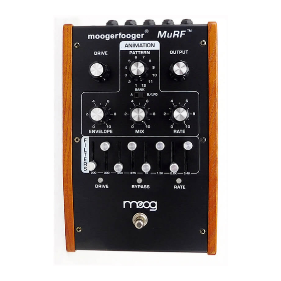
The Bass MuRF’s FILTERS The Bass MuRF’s seven resonant filters have fixed center frequencies and a shelving(lowpass) filter that has a fixed cutoff frequency. These frequencies are shown on the legend underneath the filters’ sliders. Their frequencies are: 110 Hz(shelving filter), 160 Hz, 240 Hz, 350 Hz, 525 Hz, 775 Hz, 1.2K and 1.8K. - Page 8 3) Make sure the effect is on, and MIX is at 10. 4) Connect just the “left/mono” output to your amplification You may want to experiment with the panel controls and switches as we discuss each of the parameters. 5) Now, play a bright, sustained sound, preferably of low pitch into the Bass MuRF.
- Page 9 “B/LFO”. Now as you play through the Bass MuRF, you’ll hear the filters swept up and down automatically. To change the speed of the LFO, plug a Moog EP-1 expression pedal into the LFO/SWEEP Control Input. The EP-1 can now slow down or...
-
Page 10: Envelope Generators
ENVELOPE GENERATORS Now that we have explained the Bass MuRF’s filters, let’s proceed with some more definitions to explain the Animation function of the Bass MuRF. The term “Envelope” is used to describe the changes that occur to a musical sound, from its start to its end. A musical sound can have a rapid onset, like the plucking of a string or the striking of a drum. -
Page 11: Sequencers And Pattern Generation
SEQUENCERS and PATTERN GENERATION A Sequencer is used to generate reoccurring rhythmic patterns, often by triggering sequences of notes in synthesizers or drum machines. However sequencers can be used for purposes other than triggering notes - they can be set up to create reoccurring changes of timbre as well. - Page 12 arranged in two banks of 12. An easy way to understand the Animation is to look at a simple pattern displayed on a grid. Figure 10 shows a graphic representation of pattern 2 in Bank A. The columns going left to right Figure 10 - Diagram of Pattern 2, Bank A are the steps of the pattern.
-
Page 13: The Bass Murf's Tap/Step Input
THE Bass MuRF’S TAP/STEP INPUT The Bass MuRF’s Animation can be synced to the tempo of the music using a Moog FS-1 footswitch or equivalent plugged into the TAP/STEP input. Tapping three times activates the tap tempo feature of the Bass MuRF. The MF-105B calculates the time in between taps and translates this into the rate for the pattern. -
Page 14: Audio Level Controls And Mixing
THE AUDIO LEVEL CONTROLS AND MIXING The DRIVE control adjusts the signal level at the Bass MuRF’s circuit input. With this control you can set the right input level for virtually any instrument or line-level signal source. Turn this control counterclockwise for strong input signals, and clockwise for weaker sound sources. -
Page 15: Expression Pedals And Voltage Control
Note that the odd-numbered filters are sent to the left channel, and the even-numbered filters are sent to the right channel. This allows for spreading a sound’s frequencies between two speakers, which adds a “spacious” feel. EXPRESSION PEDALS AND VOLTAGE CONTROL You now know what each of the rotary controls does to the sound of the MF-105B. -
Page 16: Some Typical Setups
MF-105B with external control signal sources in the Technical Information section on Pages 17 and 18. SOME TYPICAL SETUPS UPWARD STAIRCASE WITH RHYTHMIC VARIATION Here is a variation on the basic setting of figure 2 that shows off the abil- ity of the Bass MuRF to create rhythmic variations within the patterns. -
Page 17: Technical Information
X-FACTOR This setup shows off how long envelope times, in relation to the pattern’s rate, creates a morphing timbre. Try increasing the rate on this setup to make for a more tremu- lous effect. TECHNICAL INFORMATION NOTE: The following information is intended for use by people who understand analog electronic circuitry and have enough practical experience to interconnect sophisticated electronic equipment correctly. - Page 18 An expression pedal for use with the MF-105B should contain a 50KW or 100KW potentiometer which is connected from the sleeve to the ring terminals. Figure 14 – Correct wiring for an expression The potentiometer wiper is pedal connected to the tip terminal. The pedal cable should be shielded, with the shield connected to the sleeve terminal.
-
Page 19: Limited Warranty
During the one-year period, any defective products will be repaired or replaced, at Moog Music’s option, on a return- to-factory basis. This Warranty covers defects that Moog Music determines are no fault of the user. -
Page 20: Mf-105B Specifications
MF-105B SPECIFICATIONS DESCRIPTION: Analog effects module incorporating two functions: 7 – band Resonant Filters and 1 - band Shelving (Lowpass) Filter and a 24- Pattern Sequencer triggering Volume Envelopes for 8 Filters. FRONT PANEL FEATURES: DRIVE rotary control - adjusts the gain of the audio input to the effect. -
Page 21: General Specifications
TAP/STEP IN 1⁄4” phone jack – provides a means of syncing the tempo of the Bass MuRF’s Animation Patterns to the tempo of the music by pressing on an external footswitch (Moog FS-1, or equivalent) three times. +9V POWER INPUT jack – accepts +9VDC unregulated 300 mA power adaptor with positive center. -
Page 22: Appendix A -The Bass Murf's Patterns
APPENDIX A: THE Bass MuRF’s PATTERNS BANK A 1) No Animation 2) Upward Staircase 3) Repeater 4) X-Factor 5)Perpetual Motion... - Page 23 6) Arpeggiated Filters 7) Rhythmicon 8) Prime Number Rhythmicon 9)Double X 10) Double Dip...
- Page 24 11) Squiggly 12) Slowbeat BANK B - with LFO 1) No Animation 2) Downward Staircase 3) Down and Up...
- Page 25 4) Upward Cascade 5) Pyramid 6) Asymmetry 7) Arpeggiated Perpetual Motion...
- Page 26 8) Asymmetry 2 9)Folded Rhythmicon 10) Multi-groove 11) Breakbeat 12) Big Beat...
-
Page 27: The Murf Pattern Step Adaptor
What it is: The MuRF Pattern Step Adaptor is a female to male 1/4” adaptor that attaches to your Moog (FS-1) footswitch cable and plugs into the tap/step input allowing the user to manually “step” through the patterns generated by the sequencer. - Page 28 Notes: ©2005 Moog Music Inc. MOOG MUSIC Inc. 2004-E RIVERSIDE DRIVE ASHEVILLE, NC 28804 Phone: (828) 251 0090 FAX: (828) 254 6233 Email: info@moogmusic.com WEB SITE: www.moogmusic.com...
Need help?
Do you have a question about the Moogerfooger MF-105B Bass MuRF and is the answer not in the manual?
Questions and answers