Advertisement
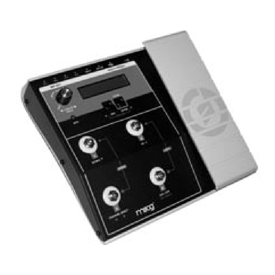
MP-201 Multi-Pedal
Table of Contents
Introduction .................................................
Overview and Features ........................
Instant Gratification ................................
Presets Defined ........................................
Operating Modes ....................................
Chart of Panel Functions ...................
Single Channel Mode ............................
Quad Channel Mode ............................
Edit Mode ....................................................
Edit Mode Menus ....................................
Storing Presets ..........................................
Userʼs Manual
4
5
8
11
12
15
16
17
19
20
21
32
Low Frequency Oscillator Parameters...............
MIDI Implementation ..................................................
Utility Mode ......................................................................
Utility Mode Menus ......................................................
Appendix A - Service & Support Info ...............
Appendix B - Caring for the Multi-Pedal .........
Appendix C - Footpedal Adjustment ................
Appendix E - Specifications .....................................
Appendix F - Factory Presets .................................
33
37
39
40
48
49
49
50
51
52
Page 3
Advertisement

Subscribe to Our Youtube Channel
Related Manuals for Moog MP-201 Multi-Pedal


Summary of Contents for Moog MP-201 Multi-Pedal
-
Page 1: Table Of Contents
MP-201 Multi-Pedal Userʼs Manual Table of Contents Introduction ..........Low Frequency Oscillator Parameters....Overview and Features ......MIDI Implementation ..........Instant Gratification ........ Utility Mode ..............Presets Defined ........Utility Mode Menus ............Controllers and Control Signals ..Operating Modes ........Appendix A - Service &... -
Page 2: Introduction
MP-201 User’s Manual Introduction Thank you and congratulations on your purchase of the MP-201 Multi-Pedal. The MP-201 Multi-Pedal is an advanced four-channel CV/MIDI footpedal controller. The analog CV control outputs consist of four 1⁄4” jacks located on the back of the unit. -
Page 3: Overview And Features
MP-201 User’s Manual Overview and Features The MP-201 Multi-Pedal has 4 analog Control Voltage (CV) outputs and USB/ standard MIDI connectors that can transmit or receive controller information on up to 4 MIDI channels simultaneously. Each CV output can be individually programmed as an analog CV with +/- 5V limits, or a Gate trigger (0V - 5V). - Page 4 MP-201 User’s Manual Here’s a brief look at the MP-201 front and back panel controls and functions: Front Panel: 1. VALUE encoder/Encoder Pushswitch - The VALUE encoder selects presets and is used to navigate through editing screens. Rotating the VALUE encoder changes presets, parameters and values.
- Page 5 MP-201 User’s Manual 6. Four Footswitch LED indicators. The Bi-color LED indicators are used to display the current ON/OFF state of the four outputs (Red LEDs) and the current level of the outputs (Amber LEDs). 7. MIDI LED - Indicates MIDI Input activity when lit. NOTE: The chart on page 16 details the function of the panel controls in all modes of operation, and is a handy reference for learning how to navigate through the MP-201’s functions.
-
Page 6: Instant Gratification
MP-201 User’s Manual Instant Gratification Follow these steps to experience some of what the MP-201 Multi-Pedal can do. Unpack and set up the Multi-Pedal. Connect the supplied AC adapter to the POW- ER IN jack on the back of the Multi-Pedal, and then make additional connections as shown. - Page 7 MP-201 User’s Manual 3. On the Multi-Pedal, use the VALUE encoder to select Preset 00 ‘EXPRESSR’. The Multi-Pedal LCD should appear as shown below. The Multi-Pedal is now configured as a standard expression pedal with a Control Voltage (CV) range of 0 to +5V. If you are connected to a Voyager or Little Phatty, playing the keyboard while adjusting the footpedal will open and close the filter.
- Page 8 MP-201 User’s Manual 2. On the Multi-Pedal, use the VALUE encoder to select Preset 33, ‘MIDI CCs’. The Multi-Pedal LCD should appear as shown below. The Multi-Pedal is now configured as an expression pedal that is setup to transmit MIDI CC messages for Mod Wheel (CC#1), Breath (CC#2), Volume (CC#7) and Foot- Ctl (CC#4) on MIDI Channel 1.
-
Page 9: Presets Defined
MP-201 User’s Manual Presets Defined A Preset is a collection of four programmed Control Channels (see figure below). Each channel can be programmed to specify a Control Voltage (CV), a MIDI Continuous Controller message, or both. There are a total of 50 presets available (Preset #00-49). -
Page 10: Controllers And Control Signals
40). It is up to the MP-201 user to know and understand the input requirements of their analog gear before connecting the MP-201. Some analog gear may not be able to accept negative voltages! All current Moog gear is compatible with the CV outputs of the MP-201, including all Moogerfooger® Analog Effects, Minimoog Voyager®... - Page 11 MP-201 User’s Manual trills, or slow rhythmic sweeps, while oscillations in the audio range can be used to create truly wild sonic effects, including frequency modulation (FM), amplitude modulation (AM), and timbre modulation. A CV can also be a randomly generated signal. If it is continuously random, it is called Noise, similar to the static white noise that can be picked up on an analog radio tuned between stations.
- Page 12 MP-201 User’s Manual MIDI MIDI was developed as a standard way of communicating control signals digitally for musical devices or software across a MIDI or USB cable. Standard MIDI cables use 5-pin DIN connectors, and each cable can send MIDI data (MIDI OUT) or receive MIDI Data (MIDI IN).
-
Page 13: Operating Modes
MP-201 User’s Manual Operating Modes The controls on the Multi-Pedal perform multiple functions as indicated on the front panel of the unit. In order to organize these functions into logical groups, the Multi- Pedal uses the concept of ‘Operating Modes’. There are four Operating Modes: - Single Channel (SGL) Mode - Quad Channel (QD) Mode - Edit Mode... -
Page 14: Chart Of Panel Functions
MP-201 User’s Manual �������������� Page 16... -
Page 15: Single Channel Mode
MP-201 User’s Manual Single Channel Mode Single Channel Mode is the default operation mode when the Multi-Pedal is first powered up. Single Channel Mode (SGL) allows you to: - view and edit the current Preset name, - view information about the current Channel - select the current Preset with footswitches. - Page 16 MP-201 User’s Manual Preset Names Preset Naming is only available in Single Channel Mode. To name a Preset, press the Encoder pushswitch. The cursor will move to the first letter in the Preset name field. Use the VALUE encoder to selected the desired character.
-
Page 17: Quad Channel Mode
MP-201 User’s Manual Quad Channel Mode Quad Channel Mode (QD) provides access to controlling all four channels at the same time. Each footswitch controls the ON/OFF state of the channel indicated by the Channel number. The movement of the footpedal will affect any of the Channels that are ON in the manner defined by the Channel Mode and settings of the Channels in the preset. -
Page 18: Edit Mode
MP-201 User’s Manual Edit Mode Edit Mode allows you to edit the parameters of a Preset. Edit Mode can be entered from Single Channel Mode or Quad Channel Mode simply by pressing EDIT or by pressing FS2 & FS4 simultaneously. In Edit Mode, the VALUE Encoder or footswitches 1 &... -
Page 19: Edit Mode Menus
MP-201 User’s Manual Edit Mode Menus The menu trees shown on the following pages will assist you in navigating through the available Preset editing parameters. Note that the menus are dynamic, which means that the available parameters change based on the selected Channel Mode. The menu trees show the parameters, values and descriptions for each menu item. - Page 20 MP-201 User’s Manual EDIT Mode menus - Common Parameters PARAMETERS: VALUES: Available character set (numbers, upper > case, lower case), 8 characters max. ON, OFF EXPRESSION, GATE, LFO OFF, 1 – 16 Default: 1 0 – 127 Default: 1 LSB 0 – 128, MSB 0 – 128 Default: OFF, 0 –...
- Page 21 Some MIDI equipment and software may not be robust enough to handle this large amount of data. Moog Music makes no guarantees of the ability of products made by other vendors to handle this amount of MIDI data.
- Page 22 MP-201 User’s Manual EDIT Mode menus - Channel Mode When Channel Mode = EXPRESSION: PARAMETERS: VALUES: EXPRESSION, GATE, LFO 0 – 4095 Default: 0 0 – 4095 Default: 4095 0 – 4095 Default: 2048 When Channel Mode = GATE: PARAMETERS: VALUES: EXPRESSION, GATE, LFO MOMENTARY, LATCH...
- Page 23 MP-201 User’s Manual DESCRIPTION: When CHANNEL MODE is set to EXPRESSION, the selected Channel will output a smoothly changing voltage corresponding to the movement of the footpedal. HEEL VALUE sets the value of the selected channel’s CV output when the footpedal is in the heel (up) position.
- Page 24 MP-201 User’s Manual EDIT Mode menus - Channel Mode When Channel Mode = LFO: PARAMETERS: VALUES: EXPRESSION, GATE, LFO TRIANGLE, SQUARE, SAW DOWN, RAMP UP, S+H RANDOM, NOISE Default: TRIANGLE RATE, AMOUNT, OFFESET Default: RATE INITIAL, CURRENT, CONTINUOUS Default: INITIAL FREE RUNNING, TAP TEMPO, CH1–...
- Page 25 MP-201 User’s Manual DESCRIPTION: When CHANNEL MODE is set to LFO, the selected channel will output either an LFO CV or Noise, depending on how the LFO parameter is programmed. LFO WAVEFORM allows you to choose either the waveform of the Low Frequency Oscillator, or Noise for the selected Channel.
- Page 26 MP-201 User’s Manual EDIT Mode menus - Channel Mode When Channel Mode = LFO (con’t): PARAMETERS: VALUES: 0 – 4095 Default: 4095 0 – 4095 Default: 2048 0 – 4095 Default: 0 – 4095 Default: 4095 0 – 4095 Default: 2048 NOTE: Values displayed as 0-4095 are ‘Precision’...
- Page 27 MP-201 User’s Manual DESCRIPTION: LFO AMOUNT sets the initial amount of the LFO CV for the selected Channel. See the section entitled Low Frequency Oscillator Parameters (page 33) for more information. LFO OFFSET sets the initial voltage offset amount of the LFO CV for the selected Channel.
- Page 28 MP-201 User’s Manual EDIT Mode menus - MIDI ALL PARAMETERS: VALUES: GLOBAL, NONE, DIN, USB, DIN/USB > Default: GLOBAL GLOBAL, NONE, DIN, USB, DIN/USB Default: GLOBAL GLOBAL, NONE, DIN OUT, USB OUT, DIN/USB OUT Default: GLOBAL GLOBAL, NONE, DIN OUT, USB OUT, DIN/USB OUT Default: GLOBAL...
- Page 29 MP-201 User’s Manual DESCRIPTION: The MIDI IN menu allows you to select the MIDI Input routing for individual Presets. The default setting is GLOBAL, which is the global MIDI IN setting from the ‘MIDI SETUP’ Utilities menu (page 40). Any setting other than GLOBAL will override the Global MIDI IN setting in ‘MIDI SETUP.
-
Page 30: Storing Presets
MP-201 User’s Manual Storing Presets The STORE function is used to save an edited Preset in Edit Mode (SAVE PRESET) or Performance Mode (SAVE PANEL). When a Preset is stored in Edit Mode, the store operation only overwrites values that have been actively edited. When a Preset is stored in Performance Mode (either Single Channel or Quad Channel Mode), the store operation overwrites initial state and value with current channel ON/OFF state and current footpedal position on any Channels that have been changed. -
Page 31: Low Frequency Oscillator Parameters
MP-201 User’s Manual Low Frequency Oscillator Parameters The LFOs in the MP-201 offer a wide variety of options for control. This section will provide the in-depth information you need to know in order to program and use the LFOs effectively. LFO WAVEFORMS The LFOs in the MP-201 offer a choice of five different waveforms, plus noise. - Page 32 MP-201 User’s Manual LFO SYNC The LFO SYNC parameter allows you to select the synchronization source of the LFO. The values are FREE RUNNING, TAP TEMPO, CH1–CH4 and MIDI CLOCK. The default value is FREE RUNNING, which means that the LFO is not synced to another source.
- Page 33 MP-201 User’s Manual CLOCKS/QUARTER TIME VALUE NOTE DISPLAY 1/32 note 1/32 Dotted 1/32 note 1/32 DOT 1/16 note 1/16 Dotted 1/16 note 1/16 DOT 1/8 note Dotted 1/8 note 1/8 DOT Quarter note Dotted quarter note 1/4 DOT Half note Dotted half note 1/2 DOT Whole note...
- Page 34 MP-201 User’s Manual LFO OFFSET The LFO OFFSET parameter sets the initial offset of the LFO when a Preset is called up. If the footpedal is programmed to control the Offset (FPEDAL MODE = OFFSET), then the initial LFO Offset value will be overridden as soon as the pedal is moved.
-
Page 35: Midi Implementation
MP-201 User’s Manual MIDI Implementation The MP-201 offers a wealth of possibilities as a MIDI controller. This section covers the MIDI configuration, as well as the MIDI Output and Input possibilities of the device. When using the MP-201 as a MIDI controller, the first thing that must be done is configure the MIDI Setup. - Page 36 MP-201 User’s Manual If that same MP-201 channel is set to LFO Mode and the MP-201 Channel is ON then the incoming MIDI CCs will affect the output based on the Footpedal Mode (Rate, Amount, or Offset). When the MP-201 channel is OFF, the LFO Off Mode (Initial, Current, Continuous) determines what happens at the output in response to MIDI CCs.
- Page 37 PC or SysEx Librarian for Mac allows a computer to receive SysEx data from the MP-201. For firmware updates and instructions for updating your MP-201 please consult the Moog Music web site: www.moogmusic.com. NOTE: For best results when sending or receiving SysEx data, make sure that LFOs are turned OFF.
-
Page 38: Utility Mode Menus
MP-201 User’s Manual Utility Mode menus PARAMETERS: VALUES: None > ON, OFF Default: Bipolar, Unipolar Default: Unipolar No values Default: Current Preset No values Default: Current Preset Page 40... - Page 39 MP-201 User’s Manual DESCRIPTION: The first Utilities menu displays the current version number of the operating system as shown. Rotate the VALUE encoder to advance through the Utility menus. CV SMOOTH allows you to turn the Control Voltage Smoothing function ON and OFF. This function works to smooth the LFO wave, and is especially effective when the LFO RATE is set to very high frequencies.
- Page 40 MP-201 User’s Manual Utility Mode menus PARAMETERS: VALUES: NONE, DIN, USB, DIN USB Default: DIN USB NONE, DIN, USB, DIN USB. Default: NONE, DIN OUT, USB OUT, DIN USB OUT Default: DIN USB OUT NONE, DIN OUT, USB OUT, DIN USB OUT Default: DIN OUT OFF, RECEIVE ONLY, SEND ONLY,...
- Page 41 MP-201 User’s Manual DESCRIPTION: MIDI In selects which connector(s) receive MIDI data. MIDI Out selects which connectors transmit MIDI data generated by the Multi-Pedal. The MERGE USB IN function allows you to mix MIDI data from the USB Input with MIDI messages generated by the Multi-Pedal and send the result to the selected output.
- Page 42 MP-201 User’s Manual Utility Mode menus PARAMETERS: VALUES: Page 44...
- Page 43 MP-201 User’s Manual DESCRIPTION: SEND ALL PRESETS allows you send the System Exclusive (SysEx) data for archiving the complete bank of Presets in the MP-201. Before selecting this function, enable the device that will receive the SysEx data. Once the remote device is enabled, press ENTER to start the data transfer.
- Page 44 MP-201 User’s Manual Utility Mode menus PARAMETERS: VALUES: Page 46...
- Page 45 MP-201 User’s Manual DESCRIPTION: RESTORE FACTORY allows you to restore the global default values and all factory Presets. Press ENTER to activate. NOTE: You should back up any Presets you wish to save prior to performing this function. See ‘SEND ALL PRESETS’ on page 45 for more information.
- Page 46 Appendix A - Service and Support Information Moog Limited Warranty Moog Music warrants its produces to be free of defects in materials or workman- ship and conforming to specifications at the time of shipment for a period of one year from the date of purchase. During the warranty period, any defective products will be repaired or replaced, at Moog Music’s option, on a return-to-factory basis.
-
Page 47: Appendix B - Caring For The Multi-Pedal
MP-201 User’s Manual Appendix B - Caring for the MP-201 Multi-Pedal Clean your MP-201 Multi-Pedal with a soft, moist cloth only – do not use solvents or abrasive detergents. Heed all safety warnings. Don’t drop the unit. If you are shipping your MP-201 Multi-Pedal to the factory for servicing, we recommend using the original shipping carton, or an ATA approved Road Case. -
Page 48: Appendix D - Midi Implementation Chart
MP-201 User’s Manual Appendix D - MIDI Implementation Chart Moog Music Date: 8/29/08 MP-201 Multi-Pedal Version 1.0 FUNCTION TRANS REMARKS Basic channel Default Changed 1-16, OFF 1-16, OFF User selectable Mode Default Messages Altered Note number Velocity Note ON Note OFF... -
Page 49: Appendix E - Specifications
MP-201 User’s Manual Appendix E - Specifications Type: Advanced Footpedal Expression Controller with 50 presets Performance Controls: ‘Gas Pedal’ style Footpedal Controller Four momentary Footswitches w/LED surround indicators User Interface: LCD Display, 2 x 16 characters Selection/Navigation controls: Edit & Enter/Store buttons Rotary Encoder (with pushswitch) MIDI LED Indicator Back Panel:... -
Page 50: Appendix F - Factory Presets
Experimentation is encouraged as always, so grab some patch cords, tweak a few set- tings, and experience the power, flexibility and versatility of the MP-201 Multi-Pedal! MP-201 Multi-Pedal User’s Manual Text and illustrations by Greg Kist, Cyril Lance & Steve Dunnington © Moog Music 2008, all rights reserved ® ® ®... - Page 51 MP-201 User’s Manual Page 53...
- Page 52 MP-201 User’s Manual Page 54...
Need help?
Do you have a question about the MP-201 Multi-Pedal and is the answer not in the manual?
Questions and answers