Advertisement
Quick Links
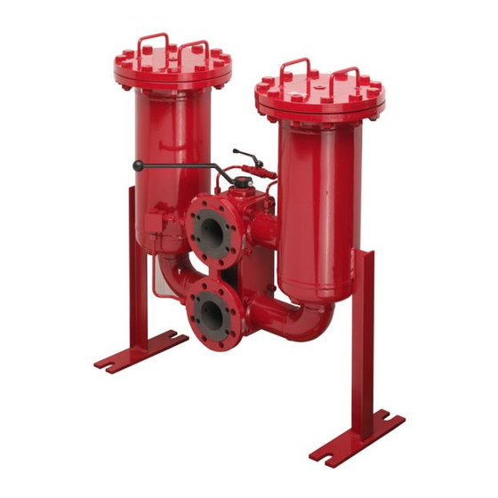
1. Maintenance
1.1 General
Please follow the maintenance instructions.
1.2 Installation
Before installing the filter into the system, check
that the operating pressure of the system does
not exceed the permitted operating pressure of
the filter.
Refer to the type code label on the filter.
Filters must be flexibly mounted and not installed
rigidly to the floor or used as a pipe support.
When installing, ensure that system forces
cannot be transferred to the filter. A filter with
a stand may only be installed to the ground if a
compensator, expansion loop or similar device
installed in the line.
1.3 Commissioning
1.3.1 Ball Change-Over
Valve "A"
Check whether or not the stipulated filter
elements are in place. Put on cover and tighten
cover screws with the stipulated torque value.
Open the ball valve in the filling tube, put the
lever into center position and fill the filter via the
system (both filter sides are filled).
Undo the vent screws on the covers by a
maximum of 1 rotation. As soon as oil begins
exiting at the vent screws, close them again.
After that, change over to a filter side by
throwing the control lever. Check the filter for
leakage.
FIL1610-1839 / 04.19
Filters
RFLD Welded Series
Service and Parts
up to 3962 gpm (15000 l/min), up to 232 psi (16 bar)
1.3.2 Segment Change-Over
Valve "B"
Check whether or not the stipulated filter
elements are in place. Put on cover and tighten
cover screws with the stipulated torque value.
Open the ball valve in the filling tube, put the
lever into center position and fill the filter via the
system (both filter sides are filled).
Lever indicates filter
not in operation.
Undo the vent screws on the covers by a
maximum of 1 rotation. As soon as oil begins
exiting at the vent screws, close them again.
After that, change over to a filter side by
throwing the control lever. Check the filter for
leakage.
1.3.3 Flap Change-Over
Valve "C"
Check whether or not the stipulated filter
elements are in place. Put on cover and tighten
cover screws with the stipulated torque value.
Open the ball valve in the filling tube. Turn
handwheel until center position is reached
(observe signs on the gear shift linkage of the
change-over valve or position indicator on the
gearbox). Fill the filter via the system (both filter
Spindle setting
sides are filled).
Left
Right
Filter in operation
Undo the vent screws on the covers by a
maximum of 1 rotation. As soon as oil begins
exiting at the vent screws, close them again.
Carefully turn the handwheel further to one
filter side. Once again, check the signs on the
gear shift linkage or position indicator on the
gearbox. These display which filter side is now
in operation. Check the filter for leakage.
1.4 Maintenance Tools
Size
Vent Plug
13XX – 150XX
VSTI G ½
Cover
Value Nm [ft-lb]
Int.
Size
plate
Hex
bolts
Steel
Hex
13XX
M20 x 70
170 [125]
30
Hex
25XX
M16 x 50
100 [74]
24
Hex
40XX
M16 x 60
100 [74]
24
Hex
52XX
M20 x 70
170 [125]
30
Hex
65XX
M24 x 70
170 [125] 140 [103]
36
Hex
78XX
M24 x 70
170 [125] 140 [103]
36
Hex
150XX M24 x 90
170 [125] 140 [103]
36
1.5 Torque Values
Type
Torque Nm[ft-lb]
VM/VD-clogging
33 [24]/100 [74]
indicators
Bowl/
Do not Torque
Lid or end cover
(See 1.3 and 2.2)
Vent
Drain
Int.
Size
Plug
Plug
Hex
VSTI
Hex 10
G1/2
1300
1320
VSTI
Hex 10
G1/2
VSTI
Hex 10
G1/2
2500 -
15020
VSTI G1
Hex 17
Int. Hex
Hex 10
Torque
Stainless
Steel
80 [59]
60 [44]
60 [44]
80 [59]
Torque Value
Nm[ft-lb]
80 [59]
80 [59]
80 [59]
200 [148]
Advertisement

Related Manuals for HYDAC International RFLD Series


Summary of Contents for HYDAC International RFLD Series
- Page 1 Filters RFLD Welded Series Service and Parts up to 3962 gpm (15000 l/min), up to 232 psi (16 bar) 1. Maintenance 1.3.2 Segment Change-Over 1.4 Maintenance Tools Valve “B” Size Vent Plug Int. Hex 1.1 General 13XX – 150XX VSTI G ½ Hex 10 Check whether or not the stipulated filter elements are in place.
-
Page 2: Filter Maintenance
FILTER MAINTENANCE 2. Element Replacement Item Ball change-over valve "A" Segment change-over valve "B" Flap change-over valve "C" 2.1 Element Removal Check that the ball valve in the filling tube is open. If not, open the ball valve. Signs on the gear shift linkage indicate which filter side is currently in operation. -
Page 3: Spare Parts
FILTER MAINTENANCE 3. Spare Parts 3.1 RFLD 13XX - 150XX 1.2/4.1 2.1 + 2.2 130X/ 250X/ 400X/ 520X/ 650X/ 780X/ 1500X/ Item Consists Designation 132X 252X 402X 522X 652X 782X 1502X Filter element See Point 4. Replacement elements 1 x 1300 3 x 0850 5 x 0850 4 x 1300... - Page 4 FILTER MAINTENANCE 4. Replacement Element Model Code 0850 R 010 ON / V B6 Size 0850, 1300, 1700, 2600 Filtration Rating (micron) 3, 5, 10, 15, 20 = ON 10 = BN4AM 3, 5, 10, = ECON2 40 = AM 25, 50, 100, 200 = W/HC = P/HC Element Media...
-
Page 5: Maintenance Instructions
FILTER MAINTENANCE 6. Maintenance Instructions 6.2 Maintenance, General This section describes maintenance work which must be carried out periodically. The operational safety and life expectancy of the filter, and 6.1 User Instructions for Filters whether it is ready for use, depend to a large extent on regular and careful maintenance. - Page 6 Montreal, Québec, Canada J2M 1K9 Edmonton, Alberta, Canada T6E 6W2 +1.905.714.9322 +1.877.539.3388 +1.780.484.4228 Mexico www.HYDACmex.com HYDAC INTERNATIONAL SA de CV Calle Alfredo A Nobel No 35 Col Puente de Vigas Tlalnepantla, Edo Mexico CP 54090 Mexico +011.52.55.4777.1262 © Copyright 2019 HYDAC TECHNOLOGY CORPORATION • Brochure - Service RFLD Welded...