
Related Manuals for Alfa Laval MAB 103B-24


Summary of Contents for Alfa Laval MAB 103B-24
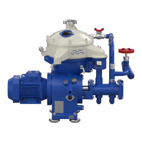
- Page 1 Separator manual High speed separator MAB 103B-24 Product No. 881145-09-02/1 Book No. 9026690-02 Rev. 2...
- Page 2 Telephone: +46 8 530 650 00 Telefax: +46 8 530 310 40 © Alfa Laval Tumba AB 09 January 2018 The original instructions are in English This publication or any part there of may not be reproduced or transmitted by any process or means without prior written permission of Alfa Laval Tumba AB.
-
Page 3: Table Of Contents
Contents Read this first Safety instructions 2.1 Warning signs in text 2.2 Recycling Information 2.3 Requirements of personnel 2.4 Remote start Separator basics 3.1 Basic principles of separation 3.2 Overview 3.3 Separating function 3.4 Mechanical function 3.5 Definitions Operating instructions 4.1 Operating routine 4.2 Cleaning the bowl Service instructions... - Page 4 6.3 Assembly 6.4 Feed and discharge pumps 6.5 Oil filling 6.6 Brake 6.7 Frame feet Trouble-tracing 7.1 Trouble tracing procedure 7.2 MAB mechanical function 7.3 Purification faults 7.4 Clarification faults Technical reference 8.1 Product description 8.2 Technical data 8.3 Gravity disc nomogram 8.4 Basic size drawing 8.5 Basic size drawing, for heater 8.6 Connection list...
- Page 5 Read and understand instruction manuals and observe the warnings before installation, operation, service and maintenance. Not following the instructions can result in serious accidents. In order to make the information clear only foreseeable conditions have been considered. No warnings are given, therefore, for situations arising from the unintended usage of the machine and its tools.
-
Page 7: Read This First
‘‘4 Operating instructions” on page If the separator has been delivered and installed by Alfa Laval as part of a processing system, this manual is a part of the System Manual. In this case, study carefully all the instructions in the System Manual. - Page 8 1 Read this first Service instructions This chapter gives instructions for daily checks, cleaning, oil changes, servicing and check points. Dismantling / Assembly This chapter contains step-by-step instructions for dismantling and assembly of the separator for service and repair. Trouble-tracing Refer to this chapter if the separator functions abnormally.
-
Page 9: Safety Instructions
Strictly follow the instructions for installation, operation and maintenance. Ensure that personnel are competent and have sufficient knowledge of maintenance and operation, especially concerning emergency stopping procedures. Use only Alfa Laval genuine spare parts and the special tools supplied. - Page 10 Use the separator only for the purpose m /h and parameter range specified by kg/m Alfa Laval. r/min Check that the gear ratio is correct for power frequency used. If incorrect, subsequent overspeed may result in a 50Hz serious break down.
- Page 11 2 Safety instructions Entrapment hazards Do NOT stand on the separator or parts Entrapment hazards Make sure that rotating parts have come to a complete standstill before starting any dismantling work. If there is no braking function the run down time can exceed two hours....
- Page 12 2 Safety instructions Crush hazards Use correct lifting tools and follow lifting instructions. Do not work under a hanging load. Noise hazards Use ear protection in noisy environments. Burn hazards Lubrication oil, machine parts and various machine surfaces can be hot and cause burns.
- Page 13 2 Safety instructions Skin irritation hazards When using chemical cleaning agents, make sure you follow the general rules and suppliers recommendation regarding ventilation, personnel protection etc. Use of lubricants in various situations. Cut hazards Sharp edges, especially on bowl discs and threads can cause cuts....
-
Page 14: Warning Signs In Text
2 Safety instructions Warning signs in text Pay attention to the safety instructions in this manual. Below are definitions of the three grades of warning signs used in the text where there is a risk for injury to personnel. DANGER Type of hazard DANGER indicates an imminently hazardous situation which, if not avoided,... -
Page 15: Recycling Information
Besides the equipment itself, any hazardous residues from the process liquid must be taken into consideration and dealt with in a proper manner. When in doubt, or in the absence of local regulations, please contact your local Alfa Laval sales company. -
Page 16: Requirements Of Personnel
2 Safety instructions Requirements of personnel Only skilled or instructed persons are allowed to operate the machine, e.g. operating and maintenance staff. Skilled person: A person with technical knowledge or sufficient experience to enable him or her to perceive risks and to avoid hazards which electricity/mechanics can create. -
Page 17: Separator Basics
3 Separator basics Contents 3.1 Basic principles of separation Factors influencing the separation 3.1.1 result 3.2 Overview 3.3 Separating function 3.3.1 Purifier bowl 3.3.2 Position of interface - gravity disc 3.3.3 Clarifier bowl 3.4 Mechanical function 3.4.1 Inlet and outlet 3.4.2 Mechanical power transmission 3.4.3... -
Page 18: Basic Principles Of Separation
3.1 Basic principles of separation 3 Separator basics Basic principles of separation The purpose of separation can be: to free a liquid of solid particles, to separate two mutually insoluble liquids with different densities while removing any solids presents at the same time, ... - Page 19 3 Separator basics 3.1 Basic principles of separation 3.1.1 Factors influencing the separation result Separating temperature For some types of process liquids (e.g. mineral oils) a high separating temperature will normally increase the separation capacity. The temperature influences oil viscosity and density and should be kept constant throughout the separation.
- Page 20 3.1 Basic principles of separation 3 Separator basics Phase proportions An increased quantity of water in a oil will influence the separating result through the optimum transporting capacity of the disc stack. An increased water content in the oil can be compensated by reducing the throughput in order to restore the optimum separating efficiency.
-
Page 21: Overview
3 Separator basics 3.2 Overview Overview The separator comprises a processing part and a driving part. It is driven by an electric motor (6). Mechanically, the separator machine frame is composed of a bottom part, a top part and a collecting cover. -
Page 22: Separating Function
3.3 Separating function 3 Separator basics Separating function Unseparated oil is fed into the bowl through the inlet pipe and is pumped via the distributor towards the periphery of the bowl. When the oil reaches holes of the distributor, it will rise through the channels formed by the disc stack where it is evenly distributed. - Page 23 3 Separator basics 3.3 Separating function 3.3.2 Position of interface - gravity disc In a purifier bowl the position of the interface should be located between the disc stack edge and the outer edge of the top disc. The position of the interface is adjusted by altering the pressure balance of the liquid phases oil and water inside the separator.
- Page 24 3.3 Separating function 3 Separator basics 3.3.3 Clarifier bowl The illustration shows characteristic parts of the clarifier bowl: 1. Discharge collar 2. Top disc without neck This bowl has one liquid outlet. The process liquid flows through the distributor to the interspaces between the bowl discs.
-
Page 25: Mechanical Function
3 Separator basics 3.4 Mechanical function Mechanical function Exploded view 3.4.1 Inlet and outlet The inlet and outlets consists of the following parts: The inlet (201). The inlet for water seal (206). The outlet for clean oil (220) from pump. ... - Page 26 3.4 Mechanical function 3 Separator basics 3.4.2 Mechanical power transmission Horizontal drive The main parts of the power transmission between motor and bowl are illustrated in the figure. The friction coupling ensures a gentle start and acceleration and at the same time prevents overloading of the worm gear and motor.
- Page 27 3 Separator basics 3.4 Mechanical function 3.4.3 Brake The separator is equipped with a hand operated brake to be used when stopping the separator. The use of the brake reduces the retardation time of the bowl and critical speeds will therefore be quickly passed.
- Page 28 3.4 Mechanical function 3 Separator basics 3.4.5 Sensors and indicators Revolution counter A revolution counter indicates the speed of the separator and is driven from the worm wheel shaft. The correct speed is needed to achieve the best separating results and for reasons of safety. The number of revolutions on the revolution counter for correct speed is shown in chapter ‘‘8.2...
-
Page 29: Definitions
3 Separator basics 3.5 Definitions Definitions Back pressure Pressure in the separator outlet. Clarification Liquid/solids separation with the intention of separating particles, normally solids, from a liquid (oil) having a lower density than the particles. Clarifier disc An optional disc, which replaces the gravity disc in the separator bowl, in the case of clarifier operation. - Page 30 3.5 Definitions 3 Separator basics...
-
Page 31: Operating Instructions
4 Operating instructions Contents 4.1 Operating routine 4.1.1 Before first start The operating procedure: 4.1.2 Selection of gravity disc 4.1.3 Before normal start 4.1.4 Starting and running-up procedure Before start 4.1.5 At full speed 4.1.6 During operation 4.1.7 Stopping procedure 4.1.8 Emergency stop Start and run-up... -
Page 32: Operating Routine
4.1 Operating routine 4 Operating instructions Operating routine These instructions is related only the separator itself. If the separator is a part of a system or module follow also the instructions for the system. 4.1.1 Before first start Technical demands for connections and logical limitations for the separator is described in the chapter ‘‘8 Technical reference”... -
Page 33: Before Normal Start
4 Operating instructions 4.1 Operating routine 4.1.3 Before normal start Check these points before every start. 1. Ensure the bowl is clean and that the separator is properly assembled. 2. Make sure that all inlet and outlet couplings and connections have been correctly made and are properly tightened to prevent leakage. -
Page 34: Starting And Running-Up Procedure
4.1 Operating routine 4 Operating instructions 4.1.4 Starting and running-up procedure 1. After starting the separator, visually check to be sure that the motor and separator have started to rotate. 2. Check the direction of rotation. The revolution counter should run clockwise. Revolution counter 3. - Page 35 4 Operating instructions 4.1 Operating routine 5. Motor current indicates when the separator has come to full speed. Current increases when the coupling engages... During start the current reaches a peak and then slowly drops to a low and stable value. For normal length of the start-up period see ‘‘8.2 Technical data”...
-
Page 36: At Full Speed
4.1 Operating routine 4 Operating instructions 4.1.5 At full speed 1. For purification mode: a. Supply water (206), approx. 1 litre (depending on Gravity disc) to form the water-seal. Continue until water flows out through the water outlet (221). The water should have the same temperature as the process liquid and be supplied quickly. -
Page 37: During Operation
4 Operating instructions 4.1 Operating routine 4.1.6 During operation Do regular checks on: oil inlet temperature (if applicable) water collecting tank level sound/vibration of the separator back pressure motor current. 4.1.7 Stopping procedure 1. Feed sealing water. 2. -
Page 38: Emergency Stop
Emergency stop hazardous when passing resonance frequencies during the run-down. After an emergency stop the cause of the fault must be identified. If all parts have been checked and the cause remains unclear contact your Alfa Laval representative for advice. -
Page 39: Cleaning The Bowl
4 Operating instructions 4.2 Cleaning the bowl Cleaning the bowl The separated sludge is accumulating on the inside surface of the separator bowl. How often the separator needs to be cleaned, depends on the amount of sediment entering the separator. High solids content or high throughput has the consequence that the cleaning need to be done more often. - Page 40 4.2 Cleaning the bowl 4 Operating instructions 3. Lock the bowl from rotating with the two lock screws. 4. Open the separator bowl. 5. Clean the bowl hood. 6. Clean the channels on the top disc upper side. 7. Remove sediment from the bowl body, clean and lubricate lock ring.
-
Page 41: Sediment Paper
4 Operating instructions 4.2 Cleaning the bowl 4.2.2 Sediment paper To facilitate the cleaning of separators, a liner of plastic paper can be inserted in the bowl. Cut the paper into shape, moisten its plastic-coated side and press it against the inside of the bowl body. When cleaning remove the paper with the sediment cake. -
Page 42: Assembling The Bowl
4.2 Cleaning the bowl 4 Operating instructions 4.2.4 Assembling the bowl Each bowl constitutes a balanced unit. Exchange of any major part necessitates rebalancing of the bowl. To prevent mixing of parts, e.g. in an installation comprising of several machines of the same type, the major bowl parts carry the machine manufacturing number or its last three digits. - Page 43 4 Operating instructions 4.2 Cleaning the bowl Clarifier bowl The arrows indicate positions of guides on the bowl parts. Lubrication needed Balanced parts. Exchange necessitates rebalancing of bowl. Clarifier bowl, exploded view 1. Clean spindle top and bowl body nave with a cloth.
- Page 44 4.2 Cleaning the bowl 4 Operating instructions 2. Bring bowl parts into positions defined by the guides. 3. Screw in both lock screws. Screw large lock ring anti-clockwise until bowl hood lies tightly against bowl body. Slacken the two lock screws. NOTE The two lock screws must be fully released to prevent risk for damage to bowl body.
-
Page 45: Service Instructions
5 Service instructions Contents 5.1 Periodic Maintenance 5.5 When changing oil 5.1.1 Introduction 5.5.1 Oil change procedure 5.1.2 Maintenance intervals 5.1.3 Maintenance procedure 5.6 Common maintenance directions 5.1.4 Service kits 5.6.1 Vibration 5.6.2 Ball and roller bearings 5.2 Maintenance Logs 5.6.3 Friction coupling 5.2.1... -
Page 46: Periodic Maintenance
5.1 Periodic Maintenance 5 Service instructions Periodic Maintenance 5.1.1 Introduction Periodic (preventive) maintenance reduces the risk of unexpected stoppages and breakdowns. Maintenance schedules are shown on the following pages in order to facilitate periodic maintenance. 5.1.2 Maintenance intervals The following directions for periodic maintenance Periodic maintenance prevent stoppages give a brief description of which components to be cleaned, checked and renewed at different... -
Page 47: Maintenance Procedure
5 Service instructions 5.1 Periodic Maintenance MS - Major Service Major Service consists of an overhaul of the complete separator every 12 months or 8000 operating hours. Seals and bearings in the bottom part are renewed. Service schedule Oil change Major Service = MS Installation 3rd year... -
Page 48: Service Kits Vibration
The contents of the service kits are described in the Spare Parts Catalogue. NOTE Always use Alfa Laval genuine parts as Major service kit otherwise the warranty will become invalid. Alfa Laval takes no responsibility for the safe operation of the equipment if non-genuine spare parts are used. -
Page 49: Maintenance Logs
Discuss your problems with an Alfa Laval representative and, when necessary, request a visit by an Alfa Laval Service engineer. Rate of corrosion and erosion and notification of cracks should also be a part of this log. Note the extent of damage and date the log entries so that the rate of deterioration can be observed. - Page 50 5.2 Maintenance logs 5 Service instructions 5.2.1 Daily checks The following steps should be carried out daily. Main component and activity Part Page Notes Inlet and outlet Check for leakage Collecting cover and connecting housing Separator bowl Check for vibration and noise Worm wheel shaft and gear casing Check for vibration and noise Check...
- Page 51 5 Service instructions 5.2 Maintenance logs 5.2.2 Oil change The oil change and check of worm gear should be carried out every 1500 * hours of operation. Main component and activity Part Page Notes Worm wheel shaft and gear housing Check Worm wheel and worm Renew...
- Page 52 5.2 Maintenance logs 5 Service instructions 5.2.3 IS - Intermediate Service Name of plant: Local identification: Separator: MAB 103B-24 Manufacture No./Year: Total running hours: Product No: 881145-09-02 Date: Signature: Main component and activity Part Page Notes Inlet and outlet Clean and inspect...
- Page 53 5 Service instructions 5.2 Maintenance logs Name of plant: Local identification: Separator: MAB 103B-24 Manufacture No./Year: Total running hours: Product No: 881145-09-02 Date: Signature: Main component and activity Part Page Notes Worm wheel shaft and gear housing Renew Oil in gear housing...
- Page 54 5.2 Maintenance logs 5 Service instructions 5.2.4 MS-Major Service Name of plant: Local identification: Separator: MAB 103B-24 Manufacture No./Year: Total running hours: Product No: 881145-09-02 Date: Signature: Main component and activity Part Page Notes Inlet and outlet Clean and inspect...
- Page 55 5 Service instructions 5.2 Maintenance logs Name of plant: Local identification: Separator: MAB 103B-24 Manufacture No./Year: Total running hours: Product No: 881145-09-02 Date: Signature: Main component and activity Part Page Notes Worm wheel shaft and gear housing Check Worm wheel and worm...
- Page 56 5.2 Maintenance logs 5 Service instructions Name of plant: Local identification: Separator: MAB 103B-24 Manufacture No./Year: Total running hours: Product No: 881145-09-02 Date: Signature: Main component and activity Part Page Notes Friction coupling Clean and check Friction coupling Renew Friction pads...
-
Page 57: Ms - Check Points
Inspect regularly for corrosion damage. Inspect frequently if the process liquid is corrosive. Always contact your Alfa Laval representative if you suspect that the largest depth of the corrosion damage exceeds 1,0 mm or if cracks have been found. Do not continue to use the... - Page 58 5.3 MS - Check points 5 Service instructions Stainless steel Stainless steel parts corrode when in contact with either chlorides or acidic solutions. Acidic solutions causes a general corrosion. The chloride corrosion is characterised by local damage such as pitting, grooves or cracks. The risk of chloride corrosion is higher if the surface is: ...
-
Page 59: Erosion
Disintegration hazard Inspect regularly for erosion damage. Inspect frequently if the process liquid is erosive. Always contact your Alfa Laval representative if the largest depth of any erosion damage exceeds 1,0 mm. Valuable information as to the nature of the damage can be recorded using photographs, plaster impressions or hammered-in lead. -
Page 60: Cracks
Always replace a part if cracks are present. It is particularly important to inspect for cracks in rotating parts. Always contact your Alfa Laval representative if you suspect that the largest depth of the damage exceeds 1,0 mm. Do not continue to use the separator until it has been inspected and cleared for operation by Alfa Laval. -
Page 61: Disc Stack Pressure
5 Service instructions 5.3 MS - Check points 5.3.4 Disc stack pressure The lock ring (1) should press the bowl hood (2) firmly against the bowl body (3). The hood in turn should exert a pressure on the disc stack (4), clamping it in place. -
Page 62: Lock Ring; Wear And Damage
If thread wear is observed, mark the bowl hood at the new position of the alignment mark on the lock ring by punching in a new alignment mark. Contact Your Alfa Laval representative If the original mark on the lock ring passes the corresponding mark on the bowl hood by more than 25°... -
Page 63: Radial Wobble Of Bowl Spindle
If wobble is too large, renew all the ball bearings on the spindle. Measure wobble after assembly. If it is still Rotate spindle by hand excessive, the spindle is probably damaged and must be replaced, contact your Alfa Laval representative. -
Page 64: Bowl Spindle Cone And Bowl Body Nave
5.3 MS - Check points 5 Service instructions 5.3.7 Bowl spindle cone and bowl body nave Impact marks on the spindle cone or in the bowl body nave may cause poor fit and out-of-balance vibrations. The bowl spindle and the nave should also be checked if the bowl spindle has been dismantled or if the bowl runs roughly. -
Page 65: Coupling Disc Of Motor
5 Service instructions 5.3 MS - Check points 5.3.8 Coupling disc of motor The position of the coupling disc on the motor shaft is establishing the location of the friction pads inside the coupling. If the coupling disc is loosened without first marking its position on the motor shaft, the correct position must be determined again. -
Page 66: Friction Pads
5.3 MS - Check points 5 Service instructions 5.3.9 Friction pads Worn or oily pads will cause a long running-up period. Replace all the pads even when only one of them is worn. If the pads are oily: Clean the pads as well as the inside of the coupling drum with a suitable degreasing agent. -
Page 67: Top Bearing Springs
5 Service instructions 5.3 MS - Check points 5.3.11 Top bearing springs Weakened or broken buffer springs may give rise to machine vibration (rough bowl running). The condition (stiffness) of a spring can hardly be determined without using special testing equipment. -
Page 68: Worm Wheel And Worm; Wear Of Teeth
5.3 MS - Check points 5 Service instructions 5.3.13 Worm wheel and worm; wear of teeth Check the teeth of worm wheel and worm for wear. ‘‘5.3.14 Tooth appearance examples” on page Examine the contact surfaces and compare the tooth profiles. The gear may operate satisfactorily even when worn to some degree. -
Page 69: Tooth Appearance Examples
5 Service instructions 5.3 MS - Check points 5.3.14 Tooth appearance examples Satisfactory teeth: Uniform wear of contact surfaces. Surfaces are smooth. Good contact surfaces will form on the teeth when the gear is subjected to only moderate load during its running-in period. Satisfactory teeth Worn teeth: Permissible wear is as a rule 1/3 of the thickness... -
Page 70: Cleaning
5.4 Cleaning 5 Service instructions Cleaning 5.4.1 External cleaning The external cleaning of the frame and motor should be restricted to brushing, sponging or wiping while the motor is running or is still hot. Use a sponge or cloth and a brush when cleaning Never wash down a separator with a direct water stream. - Page 71 It should also act as a dispersant and Alfa Laval cleaning liquid for lube oil separators is emulsifier for oil. It is recommended to use available in 25-litre plastic containers.
- Page 72 5.4 Cleaning 5 Service instructions For parts of the driving devices Use white spirit, cleaning-grade kerosene or diesel oil. Oiling (protect surfaces against corrosion) Protect cleaned carbon steel parts against corrosion by oiling. Separator parts that are not assembled after cleaning must be wiped and coated with a thin layer of clean oil and protected from dust and dirt.
-
Page 73: Cleaning Agents
5 Service instructions 5.4 Cleaning 5.4.3 Cleaning of bowl discs Bowl discs Handle the bowl discs carefully so as to avoid damage to the surfaces during cleaning. NOTE Mechanical cleaning is likely to scratch the disc surfaces causing deposits to form quicker and adhere more firmly. -
Page 74: When Changing Oil
5.5 When changing oil 5 Service instructions When changing oil Check at each oil change Check the teeth of both the worm wheel and worm for wear. 5.5.1 Oil change procedure NOTE Before adding or renewing lubricating oil in the worm gear housing, the information concerning different oil groups, handling of oils, oil change intervals etc. - Page 75 5 Service instructions 5.5 When changing oil 2. Fill new oil in the worm gear housing. The oil level should be slightly above middle of the sight glass. See chapter ‘‘8.2 Technical data” on page 125. Oil level in sight glass...
-
Page 76: Common Maintenance Directions
5.6 Common maintenance directions 5 Service instructions Common maintenance directions 5.6.1 Vibration A separator normally vibrates and make noises, when it passes its critical speeds, during the start and stop periods. It is recommended to get familiar with the normal behaviour of the machine. - Page 77 5 Service instructions 5.6 Common maintenance directions 5.6.2 Ball and roller bearings Use the greatest cleanliness when handling rolling bearings. Avoid unnecessary dismounting of bearings. Do not re-fit a used bearing, always replaced it with a new one. Important: Specially designed bearings are used for the bowl spindle.
- Page 78 5.6 Common maintenance directions 5 Service instructions NOTE Do not strike with a hammer directly on the bearing. Fitting Leave new bearings in original wrapping until ready to fit. The anti-rust agent protecting a new bearing need not to be removed. Fit a bearing on a shaft by pressure applied to the inner race and in a housing by pressure applied to Use assembly tools...
- Page 79 5 Service instructions 5.6 Common maintenance directions 5.6.3 Friction coupling If the separator does not attain full speed within about two minutes, the friction elements or the coupling may be worn or greasy. The friction elements must then be replaced with new ones or carefully cleaned from grease.
- Page 80 5.6 Common maintenance directions 5 Service instructions 5.6.4 Before shutdown Before the separator is shut-down for a period of time, the following must be carried out: Remove the bowl, according to chapter ‘‘6 Dismantling/Assembly” on page NOTE The bowl must not be left on the spindle during standstill for more than one week.
-
Page 81: Lifting Instructions
5 Service instructions 5.7 Lifting instructions Lifting instructions For lifting parts and assemblies of parts use lifting slings, working load limit (WLL): 300 kg. Lifting the separator 1. Remove the cap nut on the hinged bolt. 2. Remove the separator bowl. 3. - Page 82 5.7 Lifting instructions 5 Service instructions...
-
Page 83: Dismantling/Assembly
6 Dismantling/Assembly Contents 6.1 General 6.1.1 References to check points 6.1.2 Tools 6.2 Dismantling 6.2.1 Bowl 6.2.2 Vertical driving device 6.2.3 Horizontal driving device 6.3 Assembly 6.3.1 Vertical driving device 6.3.2 Horizontal driving device 6.3.3 Bowl 6.4 Feed and discharge pumps 6.4.1 Exchange of shear pin coupling 6.5 Oil filling... -
Page 84: General
6.1 General 6 Dismantling/Assembly General The parts must be handled carefully. Don’t place parts directly on the floor, but on a clean rubber mat, fibreboard or a suitable pallet. 6.1.1 References to check points In the text you will find references to the check point instructions in Chapter 5. -
Page 85: Dismantling
6 Dismantling/Assembly 6.2 Dismantling Dismantling To avoid accidental start, switch off and lock power supply. WARNING Entrapment hazards Make sure that rotating parts have come to a complete standstill before starting any dismantling work. The revolution counter and the motor fan indicates if separator parts are rotating or not. - Page 86 6.2 Dismantling 6 Dismantling/Assembly 3. Tighten both lock screws. The bowl parts can remain hot for a considerable time after the separator has come to a standstill. 4. Unscrew the small lock ring by using the special tool, “Spanner for small lock ring”. Left hand thread! 5.
- Page 87 6 Dismantling/Assembly 6.2 Dismantling 6. Lift off gravity disc/clarifier disc. NOTE If the gravity disc has to be replaced owing to changed operating conditions, see ‘‘8.3 Gravity disc nomogram” on page 126. Lift out the top disc, disc stack and distributor. CAUTION Cut hazard The discs have sharp edges.
- Page 88 6.2 Dismantling 6 Dismantling/Assembly 9. Remove the outlet parts. Outlet parts 10. Soak and clean all parts thoroughly in suitable cleaning agent, see ‘‘5.4 Cleaning” on page 70. Remove O-rings and replace them with spares from the major service kit. ✔...
- Page 89 6 Dismantling/Assembly 6.2 Dismantling 6.2.2 Vertical driving device Remove the outlet housings, feed and discharge pumps and raise the collecting cover. Remove also the separator bowl. Before dismantling, in the case of 8000 hours service, or if the separator vibrates while running: ✔...
- Page 90 6.2 Dismantling 6 Dismantling/Assembly 3. Force out the conical pin, using a tin hammer as a holder-on for the worm wheel shaft. 4. Use the puller-tool to first pull off the bearing and then the worm wheel. 5. Loosen the top bearing holder.
- Page 91 6 Dismantling/Assembly 6.2 Dismantling 6. Fit the cap nut to the spindle top and lift the spindle. 7. Use the puller-tool to remove the bottom bearing from the spindle. 8. Loosen and inspect the buffer springs. 9. Pull off the upper ball breaking (together with sleeve).
- Page 92 6.2 Dismantling 6 Dismantling/Assembly 10. Every 3 years: clean the oil sump. 11. Clean all dismantled parts thoroughly in a degreasing agent and check for damage and corrosion. ✔ Check point ‘‘5.3.1 Corrosion” on page Replace all parts supplied in the spare parts kit.
- Page 93 6 Dismantling/Assembly 6.2 Dismantling 6.2.3 Horizontal driving device 1. Remove the motor. CAUTION Inhalation hazard When handling friction blocks/pads use a dust mask to make sure not to inhalate any dust. Do not use compressed air for removal of any dust. Remove dust by vacuum or wet cloth.
- Page 94 6.2 Dismantling 6 Dismantling/Assembly 4. Remove the worm wheel shaft. 5. Use the puller tool to pull off the sealing washer. Protect end of worm wheel shaft with a washer. 6. To replace coupling drum or worm wheel shaft force out the spring pin and gently knock out the shaft.
-
Page 95: Assembly
6 Dismantling/Assembly 6.3 Assembly Assembly Clean all parts in a degreasing agent and replace parts supplied in the Spare parts kits. ✔ Check point ‘‘5.3.1 Corrosion” on page ‘‘5.3.2 Erosion” on page ‘‘5.3.3 Cracks” on page ‘‘5.3.11 Top bearing springs” on page ‘‘5.3.12 Ball bearing housing”... - Page 96 6.3 Assembly 6 Dismantling/Assembly 2. Lower the spindle into position. Apply some Loctite 242 onto the threads of the screw. Check for impact marks on the spindle cone and in the bowl body nave. ✔ Check point ‘‘5.3.7 Bowl spindle cone and bowl body nave”...
- Page 97 6 Dismantling/Assembly 6.3 Assembly 3. Push the worm wheel into its position on the shaft on top of the bearing. Knock with a brass sleeve on end of wheel. Observe holes for spring pin. Count the number of teeth! See Chapter ‘‘8 Technical reference”...
- Page 98 6.3 Assembly 6 Dismantling/Assembly 6. Tighten screws of sealing washer. 7. Fit the worm wheel and knock conical pin into holes. 8. Knock the bearing into position with the mounting tool and a hammer. 9. Fit the revolution counter. Lock it with the lock screw.
- Page 99 6 Dismantling/Assembly 6.3 Assembly 10. Fit pump and shear pin coupling. ‘‘6.4.1 Exchange of shear pin coupling” on page 105. 11. If the coupling disc has been loosened without first marking its position on the motor shaft, the correct position for position of coupling disc must be determined again.
- Page 100 6.3 Assembly 6 Dismantling/Assembly 6.3.3 Bowl Make sure that the check points are carried out before and during assembly of the separator bowl. ✔ Check points ‘‘5.3.7 Bowl spindle cone and bowl body nave” on page 1. Wipe off spindle top and nave bore in the bowl body.
- Page 101 6 Dismantling/Assembly 6.3 Assembly 4. Degrease lock ring threads, contact and locating faces (see arrows above). Apply Molykote 1000 paste to the threads and faces stated. Brush in the paste according to the manufacturer’s direction. 5. Secure the bowl from rotating. Screw in both lock screws.
- Page 102 6.3 Assembly 6 Dismantling/Assembly 7. Release both lock screws (A) and tighten both cap nuts (B) to a maximum torque of 12 NOTE The two lock screws must be fully released to prevent risk for damage to bowl body. B = Max. torque 12 Nm. 8.
-
Page 103: Feed And Discharge Pumps
6 Dismantling/Assembly 6.4 Feed and discharge pumps Feed and discharge pumps 1. Relief/safety valve: Examine valve cone and valve seat. 2. Bushings: Exchange the bushings if they are scratched or there is a play between shaft and bushing. 3. Wearing seals: Replace the seals if the surface is rough crackled or dented by the impeller. - Page 104 6.4 Feed and discharge pumps 6 Dismantling/Assembly 8. Axial play: The total axial play (1) must be 0,1 - 0,3 mm. If the play is too large even though the wearing seals have been renewed, it can be compensated by adding a brass leaf liner. Insert the liner at (2).
- Page 105 6 Dismantling/Assembly 6.4 Feed and discharge pumps 6.4.1 Exchange of shear pin coupling 1. Remove the pipe connections of the pump. Screw off the lock ring of the sight glass. Remove the upper gasket and the sight glass. Remove the screws of the control housing. Lift the control housing with the lower gasket and the connecting piece.
- Page 106 6.4 Feed and discharge pumps 6 Dismantling/Assembly 3. Drive out the tubular pin (a) from the worm wheel shaft. Use a counterstop. Remove the sleeve (b) from the bearing shield. 4. If the tubular pin in the impeller shaft is broken: drive out the tubular pin.
- Page 107 6 Dismantling/Assembly 6.4 Feed and discharge pumps 7. Fit the pump housing with parts. Be careful not to damage the lipseal ring. Fit the sleeve halves over the shear pin coupling. 8. Put down the control housing with connecting piece and the lower gasket. Tighten the screws.
-
Page 108: Oil Filling
6.5 Oil filling 6 Dismantling/Assembly Oil filling NOTE Before adding or renewing lubricating oil in the worm gear housing, the information concerning different oil groups, handling of oils, oil change intervals etc. given in chapter ‘‘8 Technical reference” on page 121 must be well known. -
Page 109: Brake
6 Dismantling/Assembly 6.6 Brake Brake 6.6.1 Checking of brake plug A worn or oily brake plug will lengthen the stopping time. Remove the bracket with the brake. Examine the friction element. Replace the plug when the friction material is worn. -
Page 110: Frame Feet
6.7 Frame feet 6 Dismantling/Assembly Frame feet When replacing the frame feet, the separator must be lifted. ‘‘5.7 Lifting instructions” on page NOTE Always remove the bowl before lifting the separator. When lifting and moving the separator, follow normal safety precautions for lifting large heavy objects. -
Page 111: Trouble-Tracing
7 Trouble-tracing Contents 7.1 Trouble tracing procedure Trouble-tracing 7.2 MAB mechanical function 7.2.1 The separator does not start 7.2.2 Start-up time too long Study the 7.2.3 Starting power too low System Manual’s Trouble-tracing 7.2.4 Starting power too high chapter first. Separator vibrates excessively ... -
Page 112: Trouble Tracing Procedure
Always start with trouble-tracing instructions in the System Manual, and if required, continue with the instructions below. If the problem still is not solved, contact your Alfa Laval representative. MAB mechanical function 7.2.1... -
Page 113: Starting Power Too Low
Install new bearings. Incorrect transmission (50 Hz gear and DANGER: Disintegration hazard 60 Hz power supply). STOP immediately! Install correct transmission. Contact your local Alfa Laval representative. The bowl must be inspected. Wrong direction of rotation. STOP. Adjust motor power connection. -
Page 114: Separator Vibrates Excessively During Starting Sequence
7.2 MAB mechanical function 7 Trouble-tracing 7.2.5 Separator vibrates excessively during starting sequence NOTE Some vibration is normal during starting sequence when the separator passes through its critical speeds. Possible cause Action Bowl out of balance due to: poor cleaning incorrect assembly WARNING: Disintegration hazard... -
Page 115: Smell
Possible cause Action Incorrect transmission (50 Hz gear DANGER: Disintegration hazard running on 60 Hz power supply). STOP immediately! Install correct transmission. Contact your local Alfa Laval representative. The bowl must be inspected. Frequency of power supply too high. Check. -
Page 116: Speed Too Low
7.2 MAB mechanical function 7 Trouble-tracing 7.2.10 Speed too low Possible cause Action Brake is on. Release the brake. Friction pads worn or oily. Fit new friction pads or clean the old ones if they are oily. Motor failure. Repair the motor. Top/bottom bearings damaged or worn. -
Page 117: Liquid Flows Through Bowl Casing Drain
7 Trouble-tracing 7.2 MAB mechanical function 7.2.13 Liquid flows through bowl casing drain Possible cause Action Broken water seal. Stop feed and feed water to create water seal. Too high throughput Reduce the feed. The supply of displacement/ sealing Straighten the hose or clean the strainer. Make sure water is not sufficient due to clogged the water pressure is 200-600 kPa (2-6 bar). -
Page 118: Purification Faults
7.3 Purification faults 7 Trouble-tracing Purification faults 7.3.1 Unsatisfactory separation result Possible cause Action Gravity disc hole too small. Use a gravity disc with a larger hole. Incorrect separating temperature. Adjust temperature. Throughput too high. Reduce throughput. Sludge space in bowl is filled. Empty the sludge basket in the bowl. -
Page 119: Broken Water Seal
7 Trouble-tracing 7.3 Purification faults 7.3.3 Broken water seal Possible cause Action Gravity disc too large. Use a gravity disc with a smaller hole. Separation temperature too low. Increase temperature. Throughput too high. Reduce throughput. Sealing water volume too small. Supply more water. -
Page 120: Clarification Faults
7.4 Clarification faults 7 Trouble-tracing Clarification faults 7.4.1 Unsatisfactory separation result Possible cause Action Separating temperature too low. Adjust. Throughput too high. Reduce throughput. Feed oil contains water. Re-assemble and operate the separator as a purifier. Disc stack clogged. Clean the bowl discs. Sludge space in bowl filled. -
Page 121: Technical Reference
8 Technical reference Contents 8.1 Product description 8.10.2 Exploded view 8.10.3 Water adding device (option) 8.1.1 Declaration 8.10.4 Pump 8.10.5 Foundation drawing 8.2 Technical data 8.10.6 Lifting instruction 8.10.7 Electric motor 8.3 Gravity disc nomogram 8.10.8 Machine plates and safety labels 8.4 Basic size drawing 8.11 Storage and installation 8.4.1... -
Page 122: Product Description
8.1 Product description 8 Technical reference Product description Alfa Laval ref. 9024635-06 rev. 1 Product number: 881145-09-02 Separator type: MAB 103B-24 Mineral oil Application: Technical Design: Purifier/clarifier with solid-wall separator bowl and collecting cover in aluminium. Sealings available in NITRILE.... - Page 123 8 Technical reference 8.1 Product description 8.1.1 Declaration Alfa Laval ref. 591985, rev. 8 This declaration is issued under the sole responsibility of the manufacturer. Manufacturer:................................Manufacturer address:..............................Separator type:................................Product specification:..............................Configuration number:..............................Serial number:................................Declaration of Incorporation of Partly Completed Machinery...
- Page 124 8 Technical reference The technical construction file for the machinery is compiled and retained by the authorized person Hans Thomasson within the Product Centre for High Speed Separators, Alfa Laval Tumba AB, SE-14780 Tumba Sweden. This machinery is to be incorporated into other equipment and must not be put into service until it has been completed with starting/stopping equipment, control equipment, auxiliary equipment.
-
Page 125: Technical Data
8 Technical reference 8.2 Technical data Technical data Alfa Laval ref. 556001 rev. 4 Units according to ISO Standard. The manufacturer reserves the right to change specifications without notice. Bowl speed max: 8571/ 8600 rev/min. 50Hz/60Hz Speed motor shaft max: 1500/1800 rev/min. -
Page 126: Gravity Disc Nomogram
8.3 Gravity disc nomogram 8 Technical reference Gravity disc nomogram Alfa Laval ref. 556414 rev. 0 ρ (kg/m³) 47,5 Q (m³/h) T( C) 60 70 80 90 100 110 120 130 140 150 160 170 180 190 200 212 T( F) = Density of oil in kg/m... - Page 127 8 Technical reference 8.3 Gravity disc nomogram Selection of gravity disc The best separating results are obtained by using a gravity disc with as large a hole as possible, one which will not cause a broken water seal in the bowl or an emulsification in the water outlet.
-
Page 128: Basic Size Drawing
8.4 Basic size drawing 8 Technical reference Basic size drawing Alfa Laval ref. 9024637, rev. 1 230 207 Screw 3/8-16UNC Tightening torque 16 Nm locked with lock nut ‘‘8.6 Connection list” on Data for connections see page 132... - Page 129 8 Technical reference 8.4 Basic size drawing 8.4.1 Dimensions of connections ISO-G 3/4 ISO-G1 ISO-G 3/4 Data for connections, see chapter All connections to be installed non-loaded ‘‘8.6 Connection list” on page 132 and flexible.
-
Page 130: Basic Size Drawing, For Heater
8.5 Basic size drawing, for heater 8 Technical reference Basic size drawing, for heater Alfa Laval ref. 9024636, rev. 1 Screw 3/8-16UNC Tightening torque 16 Nm locked with lock nut. ‘‘8.7 Connection list, for Data for connections see heater” on page 133... - Page 131 8 Technical reference 8.5 Basic size drawing, for heater 8.5.1 Dimensions of connections Data for connections, see chapter All connections to be installed non-loaded ‘‘8.6 Connection list” on page 132 and flexible.
-
Page 132: Connection List
8.6 Connection list 8 Technical reference Connection list Alfa Laval ref. 9024639, rev. 0 Connection No. Description Requirements/limit Inlet for process liquid, (to pump) - Permitted temperatures max. 100 °C, min. 0 °C Inlet for water seal Fresh water, approx... -
Page 133: Connection List, For Heater
8 Technical reference 8.7 Connection list, for heater Connection list, for heater Alfa Laval ref. 9024638 rev. 0 Machine with Pre-Heater. Connection No. Description Requirements/limit 201.1 Inlet for process liquid, (to pump) - Permitted temperatures max. 100 °C, min. 0 °C 201.2... -
Page 134: Interface Description
8.8 Interface description 8 Technical reference Interface description Alfa Laval ref. 9024640, rev. 0 In addition to the Connection List this document describes limitations and conditions for safe control, monitoring and reliable operation. At the end of the document a function graph and running limitations are to be found. - Page 135 8 Technical reference 8.8 Interface description Safety stop means: The machine must be stopped in the quickest and safest way due to vibrations or process reasons. Comply to following conditions: The bowl must be kept filled. The machine must not be restarted before the reason for the Safety stop has been investigated and action has been taken.
- Page 136 8.8 Interface description 8 Technical reference 8.8.3 Function graph and running limitations Stand still Starting mode Running mode Stop mode Safety stop mode...
-
Page 137: Lubricants
8 Technical reference 8.9 Lubricants Lubricants 8.9.1 Lubrication chart, general Alfa Laval ref. 553216-01, rev. 9 CAUTION Check the oil level before start. Top up when necessary. Do not overfill. Lubricating points Lubrication Interval Lubricate with oil. The oil bath... - Page 138 8.9 Lubricants 8 Technical reference...
- Page 139 Between +5 - +45 and 553218 01 – Mineral lubricating oil 1500 h frame temperature below CKC 220 (Alfa Laval oil group A) 553218 02 – Mineral lubricating oil CKE 220 (Alfa Laval oil group B) +2 - +65 553218 03 – Synthetic lubricating...
- Page 140 8 Technical reference 8.9.3 Recommended oil brands Alfa Laval ref. 553218-01, rev. 6 Mineral lubricating oil CKC 220 (Alfa Laval oil group A) Trade names and designations might vary from country to country, Please contact your local supplier for more information.
- Page 141 8.9 Lubricants 8.9.4 Recommended oil brands Alfa Laval ref. 553218-02 rev. 7 Mineral lubricating oil CKE 220 (Alfa Laval oil group B) Trade names and designations might vary from country to country, Please contact your local supplier for more information.
- Page 142 8.9 Lubricants 8 Technical reference Requirements Viscosity grade (ISO 3448/3104) VG 220 / Viscosity index (ISO 2909) VI > 90. The oil must have the correct viscosity grade. No other viscosity grade than specified should be used. The oil must be endorsed for worm gear with bronze worm wheel.
- Page 143 8 Technical reference 8.9 Lubricants 8.9.5 Recommended oil brands Alfa Laval ref. 553218-03 rev. 8 Synthetic lubricating oil PAO CKE 220 (Alfa Laval oil group D) Trade names and designations might vary from country to country, Please contact your local supplier for more information.
- Page 144 8.9 Lubricants 8 Technical reference Requirements Standard Designation ISO 12925-1, (ISO 6743/6) ISO-L-CKC/CKD/CKE/CKT 220 DIN 51517 part 3 DIN 51517 - CLP 220 NOTE The use of other lubricants than the recommended is done on the exclusive responsibility of the user or oil supplier.
- Page 145 Lubricants Alfa Laval ref. 553217-01, rev. 14 Lubricant recommendation for hygienic and non-hygienic applications Lubricants with an Alfa Laval part number are approved and recommended for use. The data in the tables below is based on supplier information. Trade names and designations might vary from country to country.
- Page 146 8.9 Lubricants 8 Technical reference Paste for assembly of metallic parts, hygienic applications (NSF registered H1 is preferred): Part No Quantity Designation Manufacturer Remark Molykote D Paste Dow Corning NSF Registered H1 537086-07 50 g Molykote P-1900 Dow Corning (7 Jan 2004) Molykote TP 42 Dow Corning...
- Page 147 8 Technical reference 8.9 Lubricants Silicone grease/oil for rubber rings, hygienic and non-hygienic applications Part No Quantity Designation Manufacturer Remark NSF Registered H1 No-Tox Food Grade Bel-Ray Silicone grease (16 December 2011) Dow Corning 360 Dow Corning Tested according to Medical Fluid and complies with all National Formulary...
- Page 148 8.9 Lubricants 8 Technical reference Always follow the lubrication recommendations of the bearing manufacturer. Grease for ball and roller bearings in electric motors Part No Quantity Designation Manufacturer Remark Energrease LS2 Energrease LS-EP2 Energrease MP-MG2 APS 2 Castrol Spheerol EPL 2 Castrol Multifak EP2 Chevron...
-
Page 149: Drawings
8 Technical reference 8.10 Drawings 8.10 Drawings 8.10.1 Cross-section of separator Cross-section of separator... - Page 150 8.10 Drawings 8 Technical reference 8.10.2 Exploded view Exploded view of separator frame...
- Page 151 8 Technical reference 8.10 Drawings 8.10.3 Water adding device (option)
- Page 152 8.10 Drawings 8 Technical reference 8.10.4 Pump Inlet and outlet pump, exploded view Inlet and outlet pump, cross-section Alfa Laval ref. 529209...
- Page 153 8 Technical reference 8.10 Drawings...
- Page 154 8.10 Drawings 8 Technical reference 8.10.5 Foundation drawing Alfa Laval ref. 556885 rev. 2 Center of separator bowl Recommended free floor space for unloading 4 holes Ø 11,5 for anchorage when doing service Service side Min. access area for overhead hoist...
- Page 155 8 Technical reference 8.10 Drawings 8.10.6 Lifting instruction Alfa Laval ref. 556213 rev. 1 Weight to lift 93 kg NOTE Never lift the separator with the separator bowl inside. Lifting the separator 1. Remove cap nut on hinged bolt 2. Remove separator bowl 3.
- Page 156 8.10 Drawings 8 Technical reference 8.10.7 Electric motor For information regarding motor specifications, see motor plate. For further information see motor manufacturer's documentation. NOTE For complete information about motor variants, please contact your Alfa Laval representative.
- Page 157 8 Technical reference 8.10 Drawings 8.10.8 Machine plates and safety labels Alfa Laval ref. 549438 rev. 3 1. Machine plate Separator Manufacturing serial No / Year Product No Frame Bowl Max. speed (bowl) Direction of rotation (bowl) Speed motor shaft El.
- Page 158 8.10 Drawings 8 Technical reference 3. Safety label Text on label: WARNING: Read the instruction manuals before installation, operation and maintenance. Consider inspection intervals. Failure to strictly follow instructions can lead to fatal injury. If excessive vibration occur, stop separator and keep bowl filled with liquid during rundown.
-
Page 159: Storage And Installation
8 Technical reference 8.11 Storage and installation 8.11 Storage and installation 8.11.1 Storage and transport of goods Storage Before storing a separator that has been in operation, make sure to drain any parts containing water, such as Operating water module (if any), Operating water system and Cooling jackets. - Page 160 8.11 Storage and installation 8 Technical reference A separator can be delivered with different types of protection: Fixed on a pallet. The separator must be stored in a storage room well protected from mechanical damage and theft and also dry and protected from rain and humidity.
- Page 161 8 Technical reference 8.11 Storage and installation Transport Specification During transport of the separator, the frame hood and bowl must always be removed from the machine. When lifting a separator it must always be hung securely. See chapter ‘‘5.7 Lifting instructions”...
- Page 162 8.11 Storage and installation 8 Technical reference 8.11.2 Planning and installation Introduction The requirements for one or more separators can be established by consulting the following documents. Basic size drawing Connection list Interface description Check the drawings when planning the installation Interconnection drawing ...
- Page 163 8 Technical reference 8.11 Storage and installation Recommendation The spanner for the large lock ring should have sufficient space to make a complete turn without hitting any of the ancillary equipment surrounding the separator. Lifting height for transport of bowl Specification ...
- Page 164 8.11 Storage and installation 8 Technical reference 8.11.3 Foundations Specification The separator should be installed at floor level, see ‘‘8.10.5 Foundation drawing” on page 154. The separator must be installed on a strong and rigid foundation to reduce the influence of vibrations from adjacent machinery.
Need help?
Do you have a question about the MAB 103B-24 and is the answer not in the manual?
Questions and answers