
Related Manuals for Cytron Technologies Enhanced SmartDrive40


Summary of Contents for Cytron Technologies Enhanced SmartDrive40
- Page 1 ROBOT . HEAD to TOE P roduct User’s Manual – M DS40B Enhanced SmartDrive40 MDS40B User's Manual Rev 1.0 December 2015 Created by Cytron Technologies Sdn. Bhd. – All Rights Reserved...
-
Page 2: Table Of Contents
M DS40B INDEX Introduction Packing List Product Specifications Board Layout Power Supply Motor Connection Safety Features Input Modes RC Input Mode Analog/PWM Input Mode Simplified Serial Mode Packetized Serial Mode Warranty Created by Cytron Technologies Sdn. Bhd. – All Rights Reserved... -
Page 3: Introduction
Besides, it also equipped with a microcontroller unit to provide smart features such as multiple input mode, current limiting and thermal protection. Enhanced SmartDrive40’s feature makes driving a robot with differential drive a truly plug and play experience. -
Page 4: Packing List
s ales@cytron.com.my immediately. ● 1 x E nhanced SmartDrive40 with top and bottom cover. ● 2 x 2 561 Servo Extension cable Created by Cytron Technologies Sdn. Bhd. – All Rights Reserved... -
Page 5: Product Specifications
– (Peak Motor Current) ** PEAK V (Logic Input – High Level) IOH V (Logic Input – Low Level) IOL 5V Output Current Depends on the room temperature. Must not exceed 1 second. Created by Cytron Technologies Sdn. Bhd. – All Rights Reserved... -
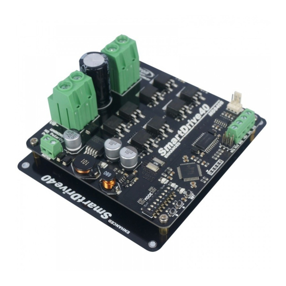
Page 6: Board Layout
Fan Input Pin Analog/PWM/Serial Input Terminal Block RC Input Pin Reset Button Motor Test Button Motor Test Button Run LED Error (ERR) LED Mode Selection DIP Switch Power Switch Terminal Block Created by Cytron Technologies Sdn. Bhd. – All Rights Reserved... - Page 7 Mode Selection DIP Switch User can select different input mode by setting the DIP switch. RC Input Pin This pins specially for RC receiver input wire. RC1 for forward/reverse and RC2 for steering. Created by Cytron Technologies Sdn. Bhd. – All Rights Reserved...
- Page 8 Analog/PWM/Serial Input Terminal Block Pin Name Description Ground. +5V output. D o not connect to another 5V source. Input 1. Input 2. *Please refer to INPUT MODE section for more detail. Created by Cytron Technologies Sdn. Bhd. – All Rights Reserved...
-
Page 9: Power Supply
10V – 45V power supply ( M ust be in parallel with a battery with same voltage ) . ● The power source can be connected to Enhanced SmartDrive40 either via the terminal block, or soldered directly to the pad at the bottom layer. ... -
Page 10: Motor Connection
RIGHT . User can further test it by controlling the motor by using RC controller. If the motor give wrong direction, reverse the polarity of the motor connection at the terminal block. Created by Cytron Technologies Sdn. Bhd. – All Rights Reserved... -
Page 11: Safety Features
Below are the detailed descriptions for each feature. a. Input Error (Error LED blinks 2 times) Every time Enhanced SmartDrive40 is power up, the input data must be ‘stop’ (for RC, Analog, PWM input mode). This feature prevent the driver from sudden run, especially when the driver accidently reset. - Page 12 8. INPUT MODE When the Enhanced SmartDrive40 is powered up, RUN LED, ERR LED and OC LED will running once. After that, the input mode will be read from the DIP switch and retained as long as the driver is powered. If you wish to change the input mode, you will need to change the setting on the DIP switch and ...
- Page 13 ROBOT . HEAD to TOE P roduct User’s Manual – M DS40B Created by Cytron Technologies Sdn. Bhd. – All Rights Reserved...
-
Page 14: Input Modes
NOTE: The RC transmitter must be ON before power up the Enhanced SmartDrive40. RC Input mode is selected by setting the S W1 & SW2 to 0 (Down) . SW3 – SW6 can be configured depending on the requirement of the user. - Page 15 RC Receiver or a microcontroller generating the RC pulse. RC Mode with RC Transmitter/Receiver (Independent), DIP switch 1 2 3 4 5 6 7 8 0 0 0 0 0 0 0 0 Created by Cytron Technologies Sdn. Bhd. – All Rights Reserved...
- Page 16 0 0 1 0 0 1 0 0 RC Mode with RC Transmitter/Receiver (Mixed Left), DIP switch 1 2 3 4 5 6 7 8 0 0 1 1 0 1 0 0 Created by Cytron Technologies Sdn. Bhd. – All Rights Reserved...
-
Page 17: Analog/Pwm Input Mode
NOTE: The Analog/PWM signal to stop the motor (2.5V if Sign-Magnitude mode is off, 0V otherwise) must be available when the Enhanced SmartDrive40 is turned on. Else, the driver will show Input Error until the correct signal is available. Analog input mode is selected by setting S W1 to 0 (Down) and SW2 to 1 (Up) . PWM input mode is selected by setting ... - Page 18 1 2 3 4 5 6 7 8 1 2 3 4 5 6 7 8 0 1 1 1 0 0 0 0 0 1 1 0 0 0 0 0 Created by Cytron Technologies Sdn. Bhd. – All Rights Reserved...
- Page 19 M DS40B PWM input mode with microcontroller (Independent Both), DIP switch DIP Switch Setting 1 2 3 4 5 6 7 8 1 0 0 0 0 1 0 0 Created by Cytron Technologies Sdn. Bhd. – All Rights Reserved...
-
Page 20: Simplified Serial Mode
8.3 SERIAL SIMPLIFIED MODE In Simplified Serial mode, Enhanced SmartDrive40 is controlled by using the UART interface. Input 1 is the UART Rx pin and Input 2 is the Slave Select pin. A single byte of data is all you need to control the speed and direction of the motor. Sending byte 127(decimal) 0r 0b01111111(binary) stops the motor, 0 is full reverse and 255 (decimal) is full forward. - Page 21 ROBOT . HEAD to TOE P roduct User’s Manual – M DS40B Figure below shows the connection to multiple Enhanced SmartDrive40 in Simplified Serial Mode. Simplified Serial mode with microcontroller (9600bps), DIP switch DIP Switch Setting 1 2 3 4 5 6 7 8 1 1 0 0 1 1 0 0 Created by Cytron Technologies Sdn.
-
Page 22: Packetized Serial Mode
(Decimal 85 or hex 55) once to the driver. The driver will then calculate the baud rate automatically based on this byte. After that, Enhanced SmartDrive40 is ready to read full packet (4 bytes) and the baud rate cannot be changed without power recycle (power off and on) or reset button. - Page 23 Figure below shows the connection to multiple drivers in Packetized Serial Mode. Packetized Serial mode with microcontroller (Address = 0), DIP switch DIP Switch Setting 1 2 3 4 5 6 7 8 1 1 1 0 0 0 0 0 Created by Cytron Technologies Sdn. Bhd. – All Rights Reserved...
-
Page 24: Warranty
No. 16, Jalan Industri Ringan Permatang Tinggi 2, Kawasan Industri Ringan Permatang Tinggi, 14100 Simpang Ampat, Penang, Malaysia. Tel: +604 - 504 1878 Fax: +604 - 504 0138 URL: www.cytron.com.my Email: s upport@cytron.com.my sales@cytron.com.my Created by Cytron Technologies Sdn. Bhd. – All Rights Reserved...
Need help?
Do you have a question about the Enhanced SmartDrive40 and is the answer not in the manual?
Questions and answers