
Related Manuals for Cytron Technologies SmartDrive40


Summary of Contents for Cytron Technologies SmartDrive40
- Page 1 ROBOT . HEAD to TOE P roduct User’s Manual – DS40A MDS40A SmartDrive40 User's Manual V1.3 Aug 2014 1 Created by Cytron Technologies Sdn. Bhd. – All Rights Reserved ...
-
Page 2: Table Of Contents
ROBOT . HEAD to TOE P roduct User’s Manual – DS40A Index Introduction and Overview 3 Packing List 4 Product Specifications 5 Board Layout 6 Power Supply 8 Motor Connection 15 Safety Features 19 Input Modes 20 8.1 R C Input Mode 21 8.2 A nalog/PWM Input Mode 24 8.3 S implified Serial Mode 29 8.4 P acketized Serial Mode 30 ... -
Page 3: Introduction And Overview
multiple input mode, current limiting and thermal protection. SmartDrive40 can also be hooked up with another similar unit and operates in pair. This ... -
Page 4: Packing List
missing, please contact us at s ales@cytron.com.my immediately. 1 x M DS40A SmartDrive40 1 x D ean T Connector (Female) User’s manual, sample source code ... -
Page 5: Product Specifications
ROBOT . HEAD to TOE P roduct User’s Manual – DS40A 3.0 PRODUCT SPECIFICATIONS Dimensions No Parameters Min Typical Max Unit 1 Input Voltage (Motor Supply Voltage) 7 25 V I (Maximum Continuous Motor Current)* 40 A MAX 2 5 minutes 30 A > 20 minutes 3 I – (Peak Motor Current) ** ... -
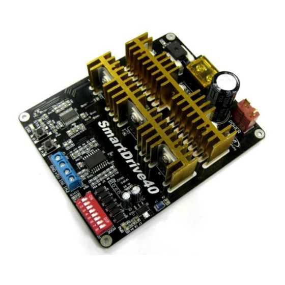
Page 6: Board Layout
ROBOT . HEAD to TOE P roduct User’s Manual – DS40A 4.0 BOARD LAYOUT Components on MDS40A and their functions: Dean T Connector (Male) – Connect to power source. For high current application, please solder the wire directly to the pad at bottom layer. ... - Page 7 ROBOT . HEAD to TOE P roduct User’s Manual – DS40A LED ERR – Error LED. The number of blinks is corresponding to the error. Number of Blinks Error Description Off No Error No error has been detected. 2 Input Error Invalid or no input detected. 3 Lipo Undervoltage The LiPo battery voltage is too low. Over current is detected and current 4 Over Current limiting is operating. 5 Over Temperature The board temperature is too high. MOSFET Driver 6 Error detected by the MOSFET driver. ...
-
Page 8: Power Supply
sources are: 6 – 18 cells NiMH or NiCd battery. ● 2 – 6 cells LiPo or LiIon battery. ● 7V – 24V sealed lead acid battery. ● 7V – 24V power supply ( M ust be in parallel with a battery with same voltage ) . ● The power source can be connected to SmartDrive40 either via the DeanT connector, or ... - Page 9 ROBOT . HEAD to TOE P roduct User’s Manual – DS40A Cut and remove the wire insulator. If user needs to solder the wire directly from battery to DeanT connector, solder o ne terminal at a time and leave another one ...
- Page 10 ROBOT . HEAD to TOE P roduct User’s Manual – DS40A Cut the shrinking tube to ~2cm each. Slide in the shrinking tube into the wire. The shrinking tube is used to protect the connection at the DeanT terminal. ...
- Page 11 ROBOT . HEAD to TOE P roduct User’s Manual – DS40A Cover the connection with shrinking tube and supply heat to it. The shrinking tube will shrink and cover the connection neatly as shown below. User may use soldering ...
- Page 12 ROBOT . HEAD to TOE P roduct User’s Manual – DS40A Steps to solder the wire directly to the pad at bottom layer are shown below: Identify the polarity of power terminal. There are + and – marking at the bottom layer ...
- Page 13 ROBOT . HEAD to TOE P roduct User’s Manual – DS40A Solder the wire to the pad at the bottom layer. Be careful while soldering and make sure the polarity is correct. ...
- Page 14 ROBOT . HEAD to TOE P roduct User’s Manual – DS40A Below is an example of power cable being soldered directly to the bottom layer. ...
-
Page 15: Motor Connection
ROBOT . HEAD to TOE P roduct User’s Manual – DS40A 6.0 MOTOR CONNECTION Similar to the power supply, connection to the motor can be made either via the terminal ... - Page 16 ROBOT . HEAD to TOE P roduct User’s Manual – DS40A Put back the screw into terminal block and tighten the screw. Repeat step 24 for another wire of DC motor. 16 Created by Cytron Technologies Sdn. Bhd. – All Rights Reserved ...
- Page 17 ROBOT . HEAD to TOE P roduct User’s Manual – DS40A This is an example connection of DC motor via terminal block. Steps to solder motor connection directly to the bottom layer pad: Cut the motor wire and remove the insulator. 17 Created by Cytron Technologies Sdn. Bhd. – All Rights Reserved ...
- Page 18 ROBOT . HEAD to TOE P roduct User’s Manual – DS40A Solder the wire to the pad at the bottom layer. Continue with another terminal as shown below. 18 Created by Cytron Technologies Sdn. Bhd. – All Rights Reserved ...
-
Page 19: Safety Features
coming out from the board if the power supply is connected at wrong polarity. LiPo Under Voltage Warning (Error LED blinks 3 times) Upon power on, SmartDrive40 will automatically detect the number of cells for the LiPo battery. If the input voltage falls below 3.3V per cell during operation, the error ... -
Page 20: Input Modes
setting on the DIP switch and power cycle the driver (Turn it off and turn it on again). In RC or Analog/PWM Input mode, two units of SmartDrive40 may be used together to ... -
Page 21: Rc Input Mode
continuously to the SmartDrive40. Instead, it only needs to send a single pulse when the speed or direction of the motor needs to be ... - Page 22 ROBOT . HEAD to TOE P roduct User’s Manual – DS40A Table below shows the commonly used DIP switch settings for RC mode. DIP Switch Mode ● RC Mode ● Single Channel Mode ● Exponential Off ● MCU Mode Off (00000000) ● RC Mode ● Single Channel Mode ● Exponential On ● MCU Mode Off (00000010) ● RC Mode ● Left Mix Mode ● Exponential Off ● MCU Mode Off (00001000) ...
- Page 23 ROBOT . HEAD to TOE P roduct User’s Manual – DS40A Figures below show the connection in RC mode for Single Channel Mode. Input 1 is connected to either a RC Receiver or a microcontroller generating the RC pulse. ...
-
Page 24: Analog/Pwm Input Mode
0V otherwise) must be available when the SmartDrive40 is turned on. Else, the driver will ... - Page 25 ROBOT . HEAD to TOE P roduct User’s Manual – DS40A when the input is > 2.5V. On – Input 1 controls the speed of the motor. Motor stops when 1 the input is 0V and run at full speed when the input is 5V. Input ...
- Page 26 ROBOT . HEAD to TOE P roduct User’s Manual – DS40A Figure below shows the connection of Analog/PWM mode for Single Channel Mode. ...
- Page 27 ROBOT . HEAD to TOE P roduct User’s Manual – DS40A Setting Up SmartDrive40 for Differential Drive System This example is based on the RC input mode. However, it can be applied for the ...
- Page 28 slower than the right motor. If this is not so, power off the SmartDrive40 and ...
-
Page 29: Simplified Serial Mode
multiple SmartDrive40 to be connected together to a single microcontroller UART port. The Slave Select pin is internally pulled high and it may be left unconnected if not used. ... -
Page 30: Packetized Serial Mode
this character. After that, SmartDrive40 is ready for command and the baud rate cannot be ... - Page 31 ROBOT . HEAD to TOE P roduct User’s Manual – DS40A Figure below shows the connection to multiple drivers in Packetized Serial Mode. 31 Created by Cytron Technologies Sdn. Bhd. – All Rights Reserved ...
-
Page 32: Warranty
ROBOT . HEAD to TOE P roduct User’s Manual – DS40A 9.0 WARRANTY ● Product warranty is valid for 12 months. ● Warranty only applies to manufacturing defect. ● Damaged caused by missuse is not covered under warranty ● Warranty does not cover freight cost for both ways. ...
Need help?
Do you have a question about the SmartDrive40 and is the answer not in the manual?
Questions and answers