
Related Manuals for Cytron Technologies FD04A


Summary of Contents for Cytron Technologies FD04A
- Page 1 ROBOT . HEAD to TOE P roduct User’s Manual – FD04A Rev2.0 FD04A Rev2.0 4 Channel Motor Driver User's Manual V1.1 Apr 2015 1 Created by Cytron Technologies Sdn. Bhd. – All Rights Reserved ...
-
Page 2: Table Of Contents
ROBOT . HEAD to TOE P roduct User’s Manual – FD04A Rev2.0 INDEX Introduction 3 Packing List 4 Product Specification And Limitations 5 Dimension 6 Board Layout 7 Hardware Installation 11 Warranty 16 ... -
Page 3: Introduction
ROBOT . HEAD to TOE P roduct User’s Manual – FD04A Rev2.0 1. INTRODUCTION FD04A Rev2.0 is an enhanced version of FD04A rev1.0. It is a motor driver board to control ... -
Page 4: Packing List
ROBOT . HEAD to TOE P roduct User’s Manual – FD04A Rev2.0 2. PACKING LIST Please check the parts and components according to the packing list. If there are any parts ... -
Page 5: Product Specification And Limitations
ROBOT . HEAD to TOE P roduct User’s Manual – FD04A Rev2.0 3. PRODUCT SPECIFICATION AND LIMITATIONS Absolute Maximum Rating Parameter Min Typical Max Unit Power Input Voltage (Motor supply voltage) 7 25 V I ( Maximum Continuous Motor Current, each 1.5 A M AX channel) I ( Peak Motor Current) 2.5 A P EAK V... -
Page 6: Dimension
ROBOT . HEAD to TOE P roduct User’s Manual – FD04A Rev2.0 4. DIMENSION ... -
Page 7: Board Layout
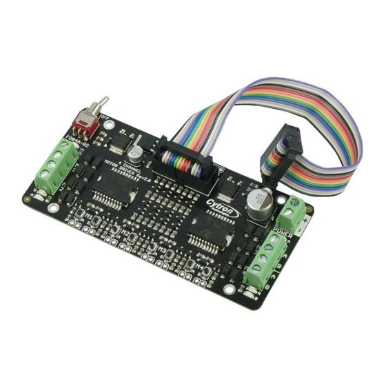
ROBOT . HEAD to TOE P roduct User’s Manual – FD04A Rev2.0 5. BOARD LAYOUT Label Function A Power toggle switch. B 5V voltage regulator C 7 x 2 IDE Socket D Extra pad E Reverse polarity protection F Power indicator LED G Power supply terminal block H Motor status indicator LED I Motor terminal block J Schottky diode K L298P motor driver L Motor test switch M 3mm hole ... - Page 8 5V at V pin . 7 x 2 IDE socket Socket to connect FD04A. Extra pad This is another alternative to access FD04A Rev2.0 control pin instead of using ribbon cable ...
- Page 9 ROBOT . HEAD to TOE P roduct User’s Manual – FD04A Rev2.0 5.1 Pin Description Figure show the pin orientation of the 7 x 2 IDE socket and extra pad. The function of each ...
- Page 10 ROBOT . HEAD to TOE P roduct User’s Manual – FD04A Rev2.0 Refer to Table 1, there are 4 individual channels which capable of driving 4 separated DC brush motor, and each channel has 2 control pins (direction pin and enable pin). ...
-
Page 11: Hardware Installation
ROBOT . HEAD to TOE P roduct User’s Manual – FD04A Rev2.0 6. HARDWARE INSTALLATION 6.1 Connecting Power Supply User may connect power supply to the POWER terminal. Please ensure the power supply voltage range within 7 25V (refer to product specification and limitation). Make sure the polarity is correct. 11 Created by Cytron Technologies Sdn. Bhd. – All Rights Reserved ... - Page 12 ROBOT . HEAD to TOE P roduct User’s Manual – FD04A Rev2.0 6.2 Connecting to DC Motor User may connect DC motor to the MOTOR terminal. There are 4 MOTOR terminals with label of M1, M2, M3 and M4. 12 ...
- Page 13 ROBOT . HEAD to TOE P roduct User’s Manual – FD04A Rev2.0 7.1 Test DC Motor User may manually test the motor by pressing the test switch. 13 Created by Cytron Technologies Sdn. Bhd. – All Rights Reserved...
- Page 14 ROBOT . HEAD to TOE P roduct User’s Manual – FD04A Rev2.0 6.4 Connecting to Microcontroller There are two methods to access the control pins of FD04A R2, which are through IDE ...
- Page 15 ROBOT . HEAD to TOE P roduct User’s Manual – FD04A Rev2.0 User can solder any suitable header pin on extra pad. Using extra pad 15 Created by Cytron Technologies Sdn. Bhd. – All Rights Reserved ...
-
Page 16: Warranty
ROBOT . HEAD to TOE P roduct User’s Manual – FD04A Rev2.0 8. WARRANTY Product warranty is valid for 12 months. ● Warranty only applies to manufacturing defect. ● Damaged caused by misuse is not covered under warranty ● Warranty does not cover freight cost for both ways. ● ... - Page 17 ROBOT . HEAD to TOE P roduct User’s Manual – FD04A Rev2.0 sales@cytron.com.my 17 Created by Cytron Technologies Sdn. Bhd. – All Rights Reserved ...
Need help?
Do you have a question about the FD04A and is the answer not in the manual?
Questions and answers