Table of Contents
Advertisement
Quick Links
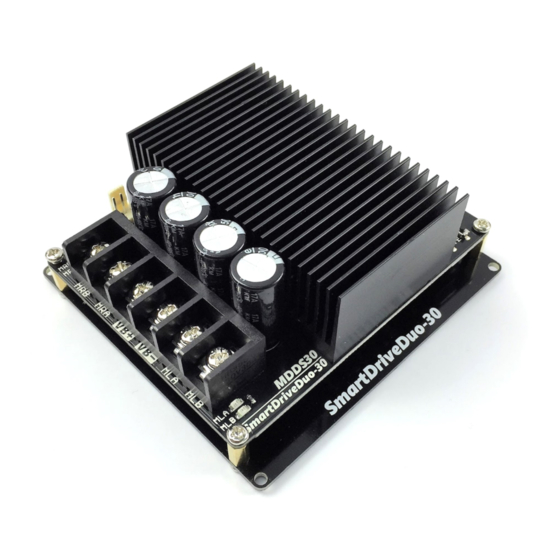
SmartDriveDuo-30
MDDS30
User's Manual
Rev 1.11
July 2019
Informa on contained in this publica on regarding device applica ons and the like is intended through
sugges on only and may be superseded by updates. It is your responsibility to ensure that your applica on
meets with your specifica ons. No representa on or warranty is given and no liability is assumed by Cytron
Technologies Incorporated with respect to the accuracy or use of such informa on or infringement of
patents or other intellectual property rights arising from such use or otherwise. Use of Cytron Technologies's
products as cri cal components in life support system is not authorized except with express wri en approval
by Cytron Technologies. No licenses are conveyed, implicitly or otherwise, under any intellectual property
rights.
Advertisement
Table of Contents

Related Manuals for Cytron Technologies SmartDriveDuo-30


Summary of Contents for Cytron Technologies SmartDriveDuo-30
- Page 1 Technologies Incorporated with respect to the accuracy or use of such informa on or infringement of patents or other intellectual property rights arising from such use or otherwise. Use of Cytron Technologies’s products as cri cal components in life support system is not authorized except with express wri en approval by Cytron Technologies.
- Page 2 ROBOT.HEAD to TOE MDDS30 Product User’s Manual - INDEX PAGES 1 . I NTRODUCTION 2 . P ACKING LIST 3 . P RODUCT SPECIFICATIONS 4 . B OARD LAYOUT 5 . P OWER SUPPLY 6 . M OTOR CONNECTION 7 . S AFETY FEATURES 8 . I NPUT MODES 8.1.
- Page 3 Product User’s Manual - 1. INTRODUCTION SmartDriveDuo-30 is one of the latest smart series motor drivers designed to drive medium power brushed DC motor with current capacity up to 80A peak (few seconds) and 30A con nuously, each channel. This driver is designed specially for controlling differen al drive mobile robot using RC controller.
-
Page 4: Packing List
Please check the parts and components according to the packing list. If there are any parts missing, please contact us at immediately. sales@cytron.io N o I TEMS Q UANTITY SmartDriveDuo-30 (Code: MDDS30 WR-EX-GROVE Grove 4 Pin Buckled 20cm Cable (Code: WR-EX-2561-03 2561 3 Ways Connector Extension Wire (Code: Op onal External Fan (Not included):... -
Page 5: Product Specifications
ROBOT.HEAD to TOE MDDS30 Product User’s Manual - 3. PRODUCT SPECIFICATIONS Dimension (unit in mm): ● MDDS30 main board. ● MDDS30 height. Created by C ytron Technologies Sdn Bhd – All Rights Reserved Back to INDEX... - Page 6 ROBOT.HEAD to TOE MDDS30 Product User’s Manual - MDDS30 bo om cover: Absolute Maximum Ra ng of SmartDriveDuo-30: N o P ARAMETERS M in T yp M ax U nit Input Voltage (Motor Supply Voltage) – (Max Con nuous Motor Current) –...
-
Page 7: Board Layout
ROBOT.HEAD to TOE MDDS30 Product User’s Manual - 4. BOARD LAYOUT L ABEL F UNCTION MOTOR RIGHT LED INDICATOR Indica on for current flow and direc on for motor RIGHT. If LED MRA turns on, means current flows from output MRA to MRB. Vice versa. MOTOR RIGHT TERMINAL BLOCK Connect to motor RIGHT at your mobile robot. - Page 8 ROBOT.HEAD to TOE MDDS30 Product User’s Manual - arrangement from le to right are as follows: NC, +ve (5V), -ve. The fan will be automa cally ON when the board’s temperature exceeds 50°C. HEAT SINK This area might be hot, please be careful. RIGHT CHANNEL LED INDICATOR RUN - Turns on when motor RIGHT is running.
-
Page 9: Power Supply
● 7V – 35V power supply. MUST BE IN PARALLEL WITH A BATTERY WITH SAME VOLTAGE The power source can be connected to SmartDriveDuo-30 either via the terminal block, or soldered directly to the pad at the bo om layer. -
Page 10: Motor Connection
ROBOT.HEAD to TOE MDDS30 Product User’s Manual - 6. MOTOR CONNECTION Similar to the power supply, connec on to the motor can be made either via the terminal block, or it can be soldered directly to the bo om layer pad. For MIXED mode, especially for RC input mode , each terminal block must be connected to the same side of the motor. -
Page 11: Safety Features
1. I nput Error ( E rror LED blinks 2 times) Every me SmartDriveDuo-30 is power up, the input data must be ‘stop’ (for RC, Analog, PWM input mode). This feature prevent the driver from sudden run, especially when the driver accidently reset. -
Page 12: Input Modes
Product User’s Manual - 8. INPUT MODES When the SmartDriveDuo-30 is powered up, RUN (Le ), ERR (Le ), RUN (Right) and ERR (Right) LEDs will running once. A er that, the input mode will be read from the DIP switch and retained as long as the driver is powered. - Page 13 ROBOT.HEAD to TOE MDDS30 Product User’s Manual - SmartDriveDuo-30 supports four different types of input mode: 1. RC (Radio Control). 2. Microcontroller Analog/PWM. 3. Serial Simplified. 4. Serial Packe zed. The DIP switch se ngs for each mode and the func on for input pin are summarized on the table below.
- Page 14 N OTE The RC transmi er must be ON before power up the SmartDriveDuo-30. RC Input mode is selected by se ng the SW1 & SW2 to 0 (Down). SW3 – SW6 can be configured depending on the requirement of the user.
- Page 15 This is useful when a microcontroller is used to control the motor. The microcontroller does not need to send the pulse con nuously to the SmartDriveDuo-30. Instead, it only needs to send a single pulse when the speed or direc on of the motor needs to be changed.
- Page 16 PWM, it can accept TTL PWM from 1.3 to 5V for HIGH level (refer to Product Specifica ons N OTE The Analog/PWM signal to stop the motor must be available when SmartDriveDuo-30 is turned on/reset. Else, the driver will show Input Error un l the correct (stop) signal is available.
- Page 17 ROBOT.HEAD to TOE MDDS30 Product User’s Manual - The speed is linear with the input signal. This is for low to medium speed motor. E xponential M ode The response to input is exponen al and thus so en the control around the center zero speed point.
- Page 18 ROBOT.HEAD to TOE MDDS30 Product User’s Manual - Created by C ytron Technologies Sdn Bhd – All Rights Reserved Back to INDEX...
- Page 19 Product User’s Manual - 8.3 Serial Simplified In Serial Simplified mode, SmartDriveDuo-30 is controlled by using the UART interface. IN1 pin is connected to the UART receive pin. IN2, AN1 and AN2 pins are not used in this mode. Serial Simplified mode is selected by se ng SW1, SW2 to 1 (Up) and SW3 to 0 (Down). SW4 –...
- Page 20 ROBOT.HEAD to TOE MDDS30 Product User’s Manual - Example Serial Simplified data: Binary bits Decimal 7 6 5 4 3 2 1 0 motor LEFT stop. motor LEFT full speed CW. motor LEFT stop.
- Page 21 (Decimal 128 or Hex 0x80 ) once to the driver. The driver will then calculate the baudrate automa cally based on this byte. A er that, SmartDriveDuo-30 is ready to read full packet (4 bytes) and the baudrate cannot be changed without power recycle (power off and on) or reset bu on.
- Page 22 ROBOT.HEAD to TOE MDDS30 Product User’s Manual - A packet consists of 4 bytes and the format is shown in the following table. V ALUE B YTE N AME D ESCRIPTION (Decimal) Header 0x55 (85) To indicate the start of packet. Used to iden fy the driver when mul ple units are Channel : connected together.
- Page 23 ROBOT.HEAD to TOE MDDS30 Product User’s Manual - 9. Assemble Optional Fan 1. Prepare the op onal accessories to mount the cooling fan. 2. Unscrew the four PCB standoffs and separate the top and bo om PCB. 3. Mount the fan to the inner side of the bo om layer PCB using screws and nuts. Make sure the airflow direc on is correct.
- Page 24 ROBOT.HEAD to TOE MDDS30 Product User’s Manual - 4. Assemble back the top and bo om PCB using the longer PCB standoffs. 5. Connect the fan to the fan connector. 6. Use the original short PCB standoffs to mount the motor driver to your pla orm to allow some clearance between the pla orm and the fan intake.
-
Page 25: Warranty
ROBOT.HEAD to TOE MDDS30 Product User’s Manual - 10. WARRANTY ● Product warranty is valid for 12 months. ● Warranty only applies to manufacturing defect. ● Damaged caused by misuse is not covered under warranty. ● Warranty does not cover freight cost for both ways. P repared by: C ytron Technologies Sdn Bhd w ww.cytron.io...
Need help?
Do you have a question about the SmartDriveDuo-30 and is the answer not in the manual?
Questions and answers
for cooling **** proper placement, manual show "label side" facing circuit board (side where wire bundle exits **** shroud). Is that correct? Manual doesn't specify, only diagram/photo.