
Related Manuals for Costar Arecont Vision ConteraIP Panoramic


Summary of Contents for Costar Arecont Vision ConteraIP Panoramic
- Page 1 ™ ConteraIP Panoramic Installation Manual 20MP AV08CPD-118 AV20CPD-118 +1.818.937.0700 www.arecontvision.com avsales@arecontvision.com...
-
Page 2: Table Of Contents
Table of Contents About Our Warranty ..........................3 Global (3 Year) Limited Warranty ......................3 Camera Overview ............................. 4 Package Contents ............................. 5 Installation ..............................7 Mounting Recommendations ........................ 7 Surface Mount ............................9 Wall Mount ............................12 Pendant Mount ............................ 15 Pole Mount ............................ -
Page 3: About Our Warranty
About Our Warranty Global (3 Year) Limited Warranty ARECONT VISION COSTAR warrants to Purchaser (and only Purchaser) (the “Limited Warranty”), that: (a) each Product shall be free from material defects in material and workmanship for a period of thirty-six (36) months from the date of shipment (the “Warranty Period”); (b) during the Warranty Period, the Products will materially conform with the specification in the applicable documentation;... -
Page 4: Camera Overview
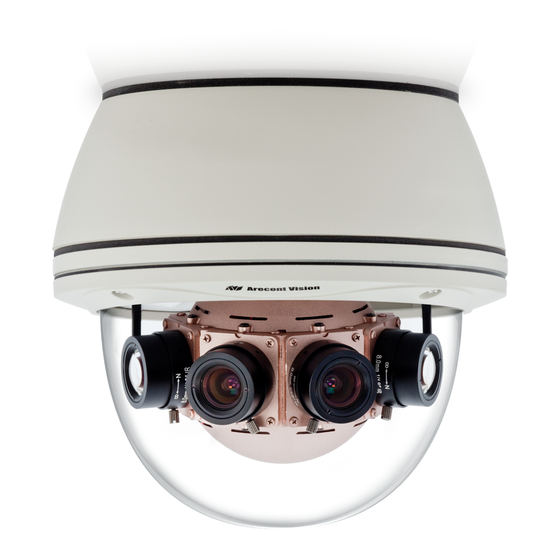
ConteraIP Panoramic ™ Megapixel Cameras Camera Overview ConteraIP Panoramic megapixel IP cameras provide an all-in-one solution for wide-area video surveillance. Four sensors and lenses are housed in an outdoor-rated IP66 and IK-10 impact-resistant dome enclosure. The cameras are available in a 180° configuration and resolutions of 8- and 20- megapixelMP). -
Page 5: Package Contents
CAUTION! Do not attempt to service a damaged unit yourself. Refer all servicing to qualified service personnel. Wiring methods shall be in accordance with the National Electrical Code/NFPA 70/ANSI, and with all local codes and authorities having jurisdiction. Wiring should be UL Listed and/or Recognized wire suitable for the application. - Page 6 ConteraIP Panoramic | Installation Manual...
-
Page 7: Installation
Installation Mounting Recommendations For the best visibility toward the target, and a minimal blind spot below the camera, Arecont Vision recommends mounting panoramic cameras 15-20ft off the ground. If the application is unable to meet this criteria, for every 10ft the camera is mounted from the ground, expect a 10ft blind spot below, and the camera should be aimed ~100ft, for every 10ft mounted from the ground, toward the horizon. - Page 8 In the example below, the camera in Figures 1D and 1E are both mounted 8ft high; however, the camera in Figure 1D is aimed 80ft toward the horizon and the camera in Figure 1E is only aimed at 30ft toward horizon.
-
Page 9: Surface Mount
Surface Mount 1. Determine a secure location to mount the camera. 2. Use the supplied security L-key, to loosen the four (4) screws securing the dome cover. Do not remove screws from the dome cover. 3. After removing the dome cover, loosen the four (4) screws and remove the bottom cover. 4. - Page 10 7. Connect the network cable to the camera’s RJ45 connector. 8. Install the main body with modules back into the back cover. Fasten securely four (4) screws you l loosen from Step#3. NOTE: Ensure the gasket between the back cover and the main body properly seated flush. ConteraIP Panoramic | Installation Manual...
- Page 11 9. Loosen the manual easing gear, and adjust the pan and tilt to obtain the desired field of view. 10. To configure the camera, reference the camera discovery, set-up and configuration section. 11. After confirming the field of view, tighten the manual easing gear (both sides) to fix the camera direction in place.
-
Page 12: Wall Mount
Wall Mount For a proper wall mount installation, the AV-WMJB-W wall mount and CP-CAP-W wall mount cap are required (sold separately). A wall mount should only be attached onto hard ceilings including wood, plastic, metal, and concrete. 1. Using the Mounting template, prepare the mounting provisions for the camera installation. 2. - Page 13 6. After removing the dome cover, loosen the four (4) screws and remove the bottom cover. 7. Install the back cover to CP-CAP-W with four (4) supplied screws. 8. Connect the network cable to the camera’s RJ45 connector. 9. Install the main body with modules back into the back cover. Fasten securely four (4) screws you loosen from Step#6.
- Page 14 11. To configure the camera, reference the camera discovery, set-up and configuration section. 12. After confirming the field of view, tighten the manual easing gear (both sides) to fix the camera direction in place. 13. Attach the dome cover back and fasten securely four captive screws. CAUTION! The captive screws must be used to properly secure the dome cover and camera housing.
-
Page 15: Pendant Mount
Pendant Mount For a proper pendant mount installation, the AV-PMJB-W pendant mount and CP-CAP-W mounting cap are required (sold separately). A pendant mount should only be attached onto hard ceilings including wood, plastic, metal, and concrete. 1. Using the Mounting template, prepare the mounting provisions for the camera installation. 2. - Page 16 6. After removing the dome cover, loosen the four (4) screws and remove the bottom cover. 7. Install the back cover to CP-CAP-W with four (4) supplied screws. 8. Connect the network cable to the camera’s RJ45 connector. 9. Install the main body with modules back into the back cover. Fasten securely four (4) screws you loosen from Step#6.
- Page 17 11. To configure the camera, reference the camera discovery, set-up and configuration section. 12. After confirming the field of view, tighten the manual easing gear (both sides) to fix the camera direction in place. 13. Attach the dome cover back and fasten securely four captive screws. CAUTION! The captive screws must be used to properly secure the dome cover and camera housing.
-
Page 18: Pole Mount
Pole Mount For a pole mount installation, the AV-WMJB-W wall mount, AV-PMA-W pole mount, and CP-CAP- W mount cap are required (sold separately). A pole mount should only be attached onto hard ceilings including wood, plastic, metal, and concrete. 1. Using the Mounting template, prepare the mounting provisions for the camera installation. 2. - Page 19 Reference # Description Steel straps with compression screws AV-WMJB-W wall mount CP-CAP-W mount cap Conduit pipe AV-PMA-W pole mount adapter Apply Teflon water seal tape to the thread of ¾” NPT pipe to avoid water leakage 7. Use the supplied two Steel Straps to attach the Pole Mount Adapter to the pole and tighten the compression screws.
-
Page 20: Corner Mount
Corner Mount For a corner mount installation, the AV-WMJB-W wall mount, AV-CRMA-W corner mount, and CP-CAP- W mount cap are required (sold separately). A corner mount should only be attached onto hard corner surfaces including wood, plastic, metal, and concrete. 1. - Page 21 Reference # Description Attach corner mount adapter to exterior 90 corner wall AV-WMJB wall mount CP-CAP-W mount cap Conduit pipe AV-CRMA-W corner mount adapter Apply Teflon water seal tape to the thread of ¾” NPT pipe to avoid water leakage 7.
-
Page 22: Electrical Box Adapter
Electrical Box Adapter The electrical box adapter is used to attach the camera to a common single, double or square electrical box. The AV-EBAS-W is required (sold separately). 1. Attach the electrical box adapter to the user supplied electrical box. 2. -
Page 23: Camera Power Up
Camera Power Up CAUTION! This product should be installed by a qualified service technician in accordance with the National Electrical Code (NEC 800 CEC Section 60) or applicable local code. Wiring methods shall be in accordance with the National Electrical Code/NFPA 70/ANSI, and with all local codes and authorities having jurisdiction. -
Page 24: Alarm I/O Functions
Alarm I/O Functions Connect the Alarm In (DI) connector to the alarm input sensor, and connect Alarm Out (DO) connector to the alarm output signal. To avoid any damaged, please follow the specification of the part as below: Alarm Out (Relay) Alarm In (Dry Contact) V sense... -
Page 25: Camera Discovery, Setup, And Configuration
Camera Discovery, Setup, and Configuration For camera discovery and setup, the AV IP Utility is recommended. The software can be found on the CD included with your camera or at: http://www.arecontvision.com/softwares.php The AV IP Utility has the ability to provide multiple discovery options, including broadcast and multicast, check the status of a camera, change camera settings, import and export camera settings via a .csv file, and update firmware and/or hardware from virtually anywhere with a network connection. -
Page 26: Web Interface Navigation
Web Interface Navigation The entire menu categories are located on the top of the web interface, and clicking on any one of the buttons will cause bottom side of the page to jump to the settings section for the selected button. The following are the camera settings available on the top of the web interface: The following are the camera settings available on the top of the web interface: •... - Page 27 • SMTP (Simple Mail Transfer Protocol) Notification • Network Storage • System • Firmware Upgrade • Reboot & Restore Settings • Date/Time • Administration • Administrator settings • Viewer Management • Support On the upper left corner, you can find the “Flip” button that allows you to flip images 180 degree. When you move the mouse over the top of each image channel, you will see the channel number.
-
Page 28: Image
Image Menu Feature Description Enable Global Mode (ON): Set up the parameters for four channels together. If Global Mode enabled, the settings of four channels will be the same and can be adjusted together. Global Mode Disable Global Mode (OFF): Set up the parameters for each channel independently. - Page 29 Auto: If Auto is selected, each channel has individual settings of the Exposure Time Control and Gain Control. AWB Mode Auto: (Auto White Balance Enables the automatic white balance feature of Mode) camera, which will automatically remove unrealistic color cast so that white color is rendered white in the image.
- Page 30 Menu Feature Description Auto detects bright backlight, glare or high contrast lighting and automatically selects the WDR level. Note: WDR enabled will decrease the FPS of Auto 20MP camera. Note: Make sure AE mode is set to "Auto". Manually adjusts the intensity of backlight compensation.
- Page 31 Stream Profiles: Balanced Mode: Limits exposure time from 0.1ms to 66ms. The camera will keep highest Balance Mode FPS when Slow Shutter is unchecked. -Slow Shutter Quality Mode: Limits exposure time from 0.1ms Quality Mode to 200ms. This mode is a good compromise between reducing noise and motion blur under most lighting conditions, but with an increase in motion blur under low light conditions.
- Page 32 IR control: On/ Off: Manually turns on or off the IR LED array. IR Level: Manually adjusts the IR intensity. IR Level Camera Name Specifies a name for the camera. The maximum length is 32 characters. Background Configures the background color of the text overlay.
- Page 33 ROI (Regions of ROI (Regions of Interest) is used to select Interest) which areas will be monitored and recorded with higher image quality while using lower image quality for other non-ROI zones to save bandwidth and storage. To setup the ROI: Select the desired channel Select Main Stream...
-
Page 34: Video & Audio
Video & Audio Menu Feature Description Select the desired channel to change video settings, or select Sync All Channels to change video settings for all Select channel four channels at once. Video Compression: Radio buttons to select the desired compression. H.265 H.264 Radio buttons to select the desired... - Page 35 Maintains variable bit rate control and maintains the bitrate under the rate limit Maximum Bitrate you set to. It can be set from 64 kbps to 8000 kbps. H.264 image quality setting for variable bit rate control. Setting a lower value results in higher image quality, higher value results H.264 Quality in lower image quality.
- Page 36 The third stream is designed for the live Video Compression: view on web interface, and the only option of Video Compression is MPJEG. MPJEG Enables the Audio In/ Audio Out features on the camera. Audio In Specifies the volume level of Audio In/ Audio Out: High, Middle, or Low.
-
Page 37: Network
Network Menu Feature Description DHCP: If checked, the camera will attempt to obtain its IP address from the DHCP server available on the network. IP Address: Sets the current IP address IP Assignment: of the camera. DHCP IP Address Subnet Mask: Once set, the camera Subnet Mask will use these mask bits to determine if... - Page 38 IPv6 Settings: Enable IPv6: Enables IPv6 function. Enable IPv6 Manually configures IPv6 address, IPv6 Address Address prefix, Default route, and Address Prefix server address. Default Route Router Advertisement Router Advertisement: Enables Router Advertisement QoS Enable Enables quality of service. QoS Video Sets DSCP value for video traffic.
- Page 39 Enable RTSP Multicast Enables RTSP Multicast stream for Stream stream 1(Main stream), stream 2(Sub Stream), and stream 3(Third Stream) Always Multicast Enables the video streams to start multicast steaming without using RTCP Video IP Configures the multicast address and the port number to stream video. Video Port Audio IP Configures the multicast address and...
- Page 40 Password Specifies the password of the DDNS account. Password Confirmation Confirms the password of the DDNS account. No SNMP Sever Disables SNMP function SNMP v2c Enables SNMP version 2 support Community String Specifies the name of the community to access to SNMP information. Trap Configuration: Specifies the destination IP address to send SNMP trap messages.
-
Page 41: Privacy Mask
Download MIB Clicks to download MIB file for SNMP. Mode Disable: Support for HTTP only. Optional: Support for HTTP and HTTPs both. Certificate Shows the current status of the Certificate Install New Certificate Locate Key PEM file Key PEM file Certificate PEM file and click Upload. - Page 42 Menu Feature Description Enable Privacy Mask Creates a privacy mask on the image so the selected areas will not be visible. Select channel Select the desired channel to add privacy masks. Drag mouse to: Select Mask to add privacy masks or Select Unmask to remove privacy masks.
- Page 43 Alignment Menu Feature Description Enable alignment Enable vertical/ horizontal alignment to allow the user to adjust vertical/ horizontal position of each channel. Select channel Select the desired channel to change vertical/ horizontal position. Vertical/ Horizontal Select Down to change image position vertically.
-
Page 44: Event
Event Menu Feature Description Enable motion Turns on and off on-camera motion detection detection. Enable extended Enables the extended motion detection motion detection and motion detection zones increase from default 64 to 1024 for enhanced motion detection sensitivity. Select channel Select the desired channel to apply motion detection. - Page 45 false motion alarms caused by image noise, higher settings will require more movement to trigger a motion event. Motion Sensitivity Sets the sensitivity to sudden overall brightness changes in the image. Enable Alarm Enables Alarm Detection (Alarm In) Detection function. Alarm Schedule Configures the alarm schedule by holding down the mouse button and...
- Page 46 Select channel Select the desired channel to enable tampering detection. Enable Tampering Enables Tampering Detection function. Detection Tampering Schedule Configures the alarm schedule by holding down the mouse button and clicking the time block to enable the schedule settings on the selected time. A light blue color on the time block indicates that the alarm schedule is enabled, while a light grey color...
- Page 47 Host Address: Specifies the host name Remote Server or IP address of the FTP server. Host Address Port: Specifies the port number of the Port FTP server. Username Username: Specifies the login Password username of the FTP server. Password: Specifies the login password of the FTP server.
- Page 48 Network Storage Enables and selects a desired trigger Handler source. The options are Trigger Alarm Detection*, Trigger Motion Detection, Trigger Tampering Alarm, and Trigger Scheduled. *This function is supported depends on models. Recipient Setup Network Storage Status: Displays the current status of the connection with Network Storage the network storage server.
- Page 49 Login Certificate Specifies the login Username Password for the network storage sever. Enable Enables and selects a desired trigger source. The options are Trigger Alarm Detection, Trigger Motion Detection, Trigger Tampering Alarm, Trigger Network Failure, Manual Record. SD Card Information Available Storage: Displays the available storage of the SD card if it is...
-
Page 50: System
System Menu Feature Description Firmware Upgrade Clicks Choose file to choose the firmware upgrade file, and then clicks Upgrade. Download Log Records all the status information of the camera in list format. Downloads the log file to the computer as a text file. Note: The log file is protected by a password. - Page 51 Time zone Server, clicks Apply NTP Server Configuration. Note: Please make sure set up appropriate gateway before configuring the NTP server. Computer System: Synchronizes the date/time information with current computer’s date/time. Once this option selected, clicks Update Time from the computer.
-
Page 52: Administration
Administration Menu Feature Description Access Control Passwords can be up to 16 letters, digits and symbols, excluding following symbols for passwords without encoding # % & ' " < > / [ ] { } _ ( ) = . + , Administrator Username: The username of... - Page 53 Set/ Erase User Viewer Name: Specifies the user name. It must be at least five and up to sixteen characters. User Viewer Password: Specifies the password for the viewer. Confirmation: Re-enters the password for the password validation. Access Level: Defines the authorization level for the user: Admin or Viewer.
-
Page 54: Support
Support Menu Feature Description Support Provides several useful hyperlinks to get more information of the camera. ConteraIP Panoramic | Installation Manual... - Page 55 © 2019 Arecont Vision Costar All rights reserved. No part of this publication may be reproduced by any means without written permission from Arecont Vision. The information in this publication is believed to be accurate in all respects. However, Arecont Vision cannot assume responsibility for any consequences resulting from the use thereof.
- Page 56 150 mm...
Need help?
Do you have a question about the Arecont Vision ConteraIP Panoramic and is the answer not in the manual?
Questions and answers