Table of Contents
Advertisement
Labkotec Oy
Myllyhaantie 6
FI-33960 PIRKKALA
FINLAND
Tel.: +358 29 006 260
Fax: +358 29 006 1260
24.9.2019
Internet: www.labkotec.fi
D15233FE-2
1/14
SET-1000
Level switch for one sensor
Installation and Operating Instructions
Copyright © 2019 Labkotec Oy
We reserve the right for changes without notice
Advertisement
Table of Contents

Related Manuals for Labkotec SET-1000

Summary of Contents for Labkotec SET-1000
- Page 1 FI-33960 PIRKKALA FINLAND Tel.: +358 29 006 260 Fax: +358 29 006 1260 24.9.2019 Internet: www.labkotec.fi D15233FE-2 1/14 SET-1000 Level switch for one sensor Installation and Operating Instructions Copyright © 2019 Labkotec Oy We reserve the right for changes without notice...
-
Page 2: Table Of Contents
Appendix 2 Electrical parameters ..............13 SYMBOLS Warning / Attention Pay special attention to installations at explosive atmospheres Device is protected by double or reinforced insulation Copyright © 2019 Labkotec Oy 2/14 We reserve the right for changes without notice... -
Page 3: General
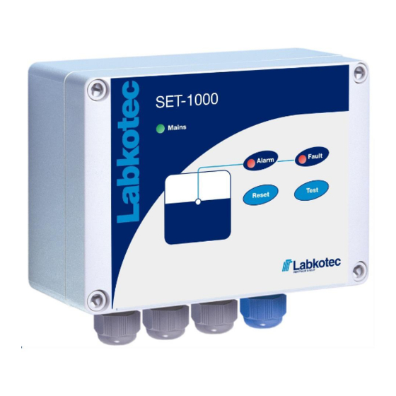
1. Figure 1. SET-1000 level switch – features SET-1000 can be used as a controller of a level sensor located in potentially explosive atmosphere (zone 0,1 or 2) due to intrinsically safe inputs of the device. The SET-1000 itself must be installed in a non- hazardous area. -
Page 4: Installation
D15233FE-2 Installation and Operating Instructions INSTALLATION The SET-1000 can be wall-mounted. The mounting holes are located in the base plate of the enclosure, beneath the mounting holes of the front cover. The connectors of the external conductors are isolated by separating plates. -
Page 5: Cabling When Using Cable Junction Box
If the sensor cable must be extended or there is need for equipotential grounding, it can be done with the cable junction box. The cabling between the SET-1000 control unit and the junction box should be done with a shielded twisted pair instrument cable. -
Page 6: Cabling When Using Cable Joint
If the sensor cable must be extended and there is a need for equipotential grounding, it should be done with the junction box LJB2. The cabling between the SET-1000 control unit and the junction box should be done with a shielded twisted pair instrument cable. -
Page 7: Operation And Settings
D15233FE-2 Installation and Operating Instructions OPERATION AND SETTINGS The SET-1000 control unit is initialized at the factory as follows. See a more detailed description in chapter 3.1 Operation. Channel 1 Alarm takes place when the level hits the sensor (high level alarm) -
Page 8: Altering Settings
Trigger point of an alarm in the sensor’s sensing element. Trigger level Sensor selection SET/DM3AL sensor or other Labkotec SET series sensor. Buzzer The buzzer can be disabled. The following tasks must only be executed by a person with proper education and knowledge of Ex-i devices. - Page 9 SENSOR SELECTION If the sensor in use is a conductive SET/DM3AL sensor, then the jumper beside the channel 1 connector must be short- circuited. Copyright © 2019 Labkotec Oy 9/14 We reserve the right for changes without notice...
-
Page 10: Trouble-Shooting
3.4 Connect the wire back to the connector. If the problem can not be solved with the above instructions, please contact Labkotec Oy’s local distributor or Labkotec Oy’s service. Attention ! If the sensor is located in an explosive atmosphere, the... -
Page 11: Repair And Service
In case of queries, please contact Labkotec Oy’s service. SAFETY INSTRUCTIONS SET-1000 level switch must not be installed in explosive atmosphere. Sensors connected to it may be installed in explosive atmosphere zone 0,1 or 2. In case of installations in explosive atmospheres the national requirements and relevant standards as IEC/EN 60079-25 and/or IEC/EN 60079-14 must be taken into account. -
Page 12: Appendices
Year of manufacture xxx x xxxxx xx YY x where YY = year of manufacture See serial number from the type (e.g. 19 = 2019) plate Copyright © 2019 Labkotec Oy 12/14 We reserve the right for changes without notice... -
Page 13: Appendix 2 Electrical Parameters
When installing the device, make sure that the electrical values of the cable between SET-1000 and sensor never exceed maximum electrical parameters. The cabling between SET-1000 control unit and cable extension junction box / cable joint must be executed as in figure 4 / 8 Extension cable should be shielded paired twisted instrument cable.
Need help?
Do you have a question about the SET-1000 and is the answer not in the manual?
Questions and answers