Labkotec SET-2000 Installation And Operating Instructions Manual
110 vac supply voltage level switch for two sensors
Hide thumbs
Also See for SET-2000:
- Lnstallation and operating lnstructions (14 pages) ,
- Installation and operating instructions manual (15 pages)
Table of Contents
Advertisement
Quick Links
Installation and Operating Instructions
Copyright © 2019 Labkotec Oy
Labkotec Oy
Myllyhaantie 6
FI-33960 PIRKKALA
FINLAND
Tel:
+ 358 29 006 260
Fax:
+ 358 29 006 1260
Internet:
www.labkotec.fi
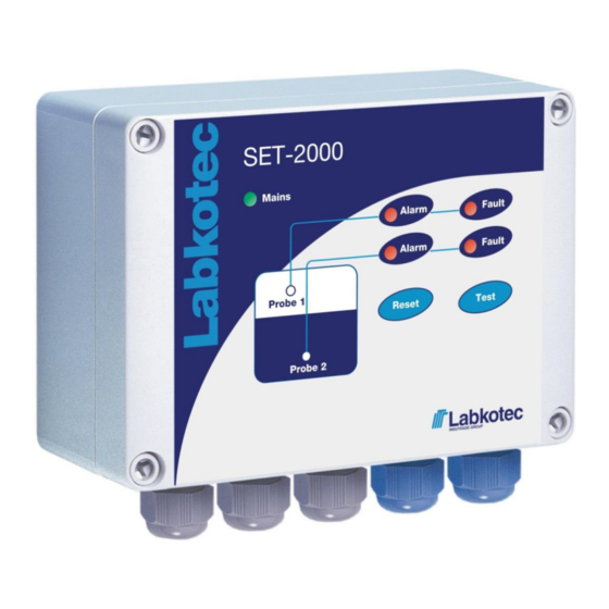
SET-2000
110 VAC supply voltage
Level switch for two sensors
We reserve the right for changes without notice
13.8.2019
D15349AE-1
1/15
Advertisement
Table of Contents

Related Manuals for Labkotec SET-2000


Summary of Contents for Labkotec SET-2000
- Page 1 + 358 29 006 260 Fax: + 358 29 006 1260 13.8.2019 Internet: www.labkotec.fi D15349AE-1 1/15 SET-2000 110 VAC supply voltage Level switch for two sensors Installation and Operating Instructions Copyright © 2019 Labkotec Oy We reserve the right for changes without notice...
-
Page 2: Table Of Contents
Appendix 2 Cabling and electrical parameters ..........13 SYMBOLS Warning / Attention Pay attention to installations at potentially explosive atmospheres Device is protected by double or reinforced insulation Copyright © 2019 Labkotec Oy 2/15 We reserve the right for changes without notice... -
Page 3: General
SET-2000 can be used as a controller of level sensors located in potentially explosive atmospheres (zone 0,1 or 2) due to intrinsically safe inputs of the device. The SET-2000 itself must be installed in a non-hazardous area. The level sensors, which are connected to SET-2000, can be installed in zones of different classification, because the channels are galvanically isolated from each other. -
Page 4: Installation
D15349AE-1 Installation and Operating Instructions INSTALLATION The SET-2000 can be wall-mounted. The mounting holes are located in the base plate of the enclosure, beneath the mounting holes of the front cover. The connectors of the external conductors are isolated by separating plates. -
Page 5: Cabling When Using Cable Junction Box
If the sensor cable must be extended or there is need for equipotential grounding, it can be done with the cable junction box. The cabling between the SET-2000 control unit and the junction box should be done with a shielded twisted pair instrument cable. -
Page 6: Level Sensors In Different Areas And Zones
Make sure, that the junction is closed properly. Copyright © 2019 Labkotec Oy 6/15 We reserve the right for changes without notice... -
Page 7: Operation And Settings
D15349AE-1 Installation and Operating Instructions OPERATION AND SETTINGS The SET-2000 control unit is initialized at the factory as follows. See a more detailed description in chapter 3.1 Operation. Channel 1 Alarm takes place when the level hits the sensor (high level alarm) -
Page 8: Altering Settings
Trigger point of an alarm in the sensor’s sensing element. Trigger level Sensor selection SET/DM3AL sensor or other Labkotec SET series sensor. Buzzer The buzzer can be disabled. The following tasks must only be executed by a person with proper education and knowledge of Ex-i devices. - Page 9 This setting is also used, when an alarm of an oil-layer on water is required by using a capacitive Labkotec SET sensor. When the switch is in its high position the Alarm LED indicator as well as buzzer will be on and the relay de- energizes when the liquid level is above the sensor’s trigger...
-
Page 10: Trouble-Shooting
The sensor might also be broken. To do: 1. Make sure, that the sensor cable has been connected correctly to the SET-2000 control unit. See sensor specific instructions. 2. Measure the voltage separately between the poles 10 and 11 as well as 13 and 14. -
Page 11: Repair And Service
In case of queries, please contact Labkotec Oy’s service. SAFETY INSTRUCTIONS SET-2000 level switch must not be installed in explosive atmosphere. Sensors connected to it may be installed in explosive atmosphere zone 0, 1 or 2. -
Page 12: Appendices
Manufacturing year: xxx x xxxxx xx YY x Please see the serial number on where YY = manufacturing year the type plate (e.g. 19 = 2019) Copyright © 2019 Labkotec Oy 12/15 We reserve the right for changes without notice... -
Page 13: Appendix 2 Cabling And Electrical Parameters
SET-2000 and sensors never exceed maximum electrical parameters. The cabling between SET-2000 control unit and cable extension junction box must be executed as in figures 5 and 6. Extension cable should be shielded paired twisted instrument cable. Due to non-linear characteristics of the sensor voltage, the interaction of both, capacitance and inductance, must be taken into account.
Need help?
Do you have a question about the SET-2000 and is the answer not in the manual?
Questions and answers