Nedap TRANSIT Ultimate Installation Manual
Hide thumbs
Also See for TRANSIT Ultimate:
- Installation manual (36 pages) ,
- Quick reference manual (6 pages)

Subscribe to Our Youtube Channel
Related Manuals for Nedap TRANSIT Ultimate


Summary of Contents for Nedap TRANSIT Ultimate
- Page 1 TRANSIT Ultimate installation guide 2020-05-13 | v5.08 | Doc. no. 5481104 www.nedapidentification.com...
-
Page 2: Table Of Contents
TRANSIT Ultimate | installation guide Contents Introduction ..................................4 Product description..............................4 Ultimate features ..............................5 Installation ..................................6 Safety precautions ..............................6 Installation guidelines ............................. 6 Mounting instructions .............................. 7 2.3.1 TRANSIT Ultimate dimensions ........................... 7 2.3.2 Wall mounting ..............................8 2.3.3... - Page 3 TRANSIT Ultimate | installation guide 4.5.1 Proximity antenna ............................. 26 4.5.2 Nedap antenna modulation ..........................27 Firmware update ................................28 Configuration ..................................29 Ultimate mode ................................ 29 Range beeper ................................. 30 Serial communication select ..........................30 Frequency select ..............................31 6.4.1...
-
Page 4: Introduction
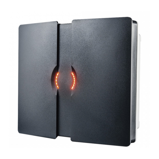
1 Introduction 1.1 Product description The TRANSIT Ultimate is a long-range reader, based on semi active RFID technology, which enables automatic vehicle identification at distances of up to 10 meters (33 ft.) and speeds of up to 200 km/h (125 mph). -
Page 5: Ultimate Features
Receive, decrypt and verify the encrypted challenge response from the tag. When the authentication is successful, the id-number is transmitted on the communication output(s). The TAB board may be bypassed to make the TRANSIT Ultimate backwards compatible with the TRANSIT Standard. See chapter 6.1. -
Page 6: Installation
• The TRANSIT Ultimate shall only be installed and serviced by qualified service personnel. • To be sure of safety, do not modify or add anything other than mentioned in this manual or indicated by NEDAP. • 2.2 Installation guidelines The TRANSIT Ultimate can be installed in any position. -
Page 7: Mounting Instructions
See the following chapters for details about the dimensions of the reader and the mounting brackets and the locations of the mounting positions. 2.3.1 TRANSIT Ultimate dimensions The picture below shows the dimensions of the TRANSIT Ultimate. All dimensions are in mm. To guarantee water tightness in all... -
Page 8: Wall Mounting
The Wall Mounting Set is supplied with the TRANSIT Ultimate reader. When the Wall Mounting Set is assembled mount it to the wall (or to the Pole Mounting Set) based on the dimensions in Figure 3. The TRANSIT Ultimate can be “aimed”... -
Page 9: Pole Mounting
TRANSIT Ultimate | installation guide 2.3.3 Pole mounting The TRANSIT Ultimate can be mounted to round poles with maximum diameter of 190 mm and square poles with maximum diameter of 150 mm using the Pole Mounting Kit. The Pole Mounting Kit has to be ordered separately (art. no. 5626595). -
Page 10: Weather Protection Hood
TRANSIT Ultimate | installation guide 2.3.4 Weather protection hood The Weather Protection hood is recommended when the reader is installed in direct sunlight. The Weather Protection Hood has to be ordered separately (art. no. 9218327). Figure 5: Dimensions Weather Protection Hood... -
Page 11: Installing The Security Key Pack
The optional Security Key Pack (SAM) has to be ordered separately (art. no. 9216537) and is required for the TRANSIT Ultimate to perform the encrypted authentication on the Ultimate tags. Please follow the procedure below to install the Security Key Pack into the TRANSIT Ultimate. Security Key Pack installation procedure Insert the Security Key Pack (SAM) into the TAB board. -
Page 12: Installing A Communication Board
TRANSIT Ultimate | installation guide 2.5 Installing a communication board The TRANSIT Ultimate features an on-board USB port and a Wiegand / Magstripe / Barcode interface. See chapter 4.3 for more details. Other communication interfaces can modularly be installed in the reader by means of a communication interface board. -
Page 13: Osdp Interface Board
TRANSIT Ultimate | installation guide 3 OSDP Interface Board For supporting OSDP on the TRANSIT Ultimate it is required to use the OSDP Interface Board, which includes the PCC485/OSDP converter. This board implements the OSDP protocol according to the SIA OSDP v2.1.7 standard, including the Secure Channel Protocol. -
Page 14: Rs485-Osdp Wiring
TRANSIT Ultimate | installation guide 3.2 RS485-OSDP wiring The RS485-OSDP wiring should be connected to the RS485 connections on the OSDP Installation Board (OSDP-IB) or directly to the PCC485. See wiring picture below. For point-to-point communication enable the termination resistor. PCC485 switch 1 to ON position. See picture below. -
Page 15: Transit Configuration
Configuration settings The relay activation and LED control must both be set to manual mode. This is best done using the NEDAP P81TEST software. Download this software from our partner portal https://portal.nedapidentification.com. Start NEDAP P81TEST software and connect to the reader using the USB or RS232 interface. -
Page 16: Connections
See chapter 4.3 Read-disable input Relay output See chapter 4.4.2 See chapter 4.4.1 General purpose inputs Tamper switch See chapter 4.4.4 See chapter 4.4.3 Proximity antenna Antenna modulation See chapter 4.5.1 See chapter 4.5.2 Figure 11: TRANSIT Ultimate connections overview 16/40... -
Page 17: Power Supply
TRANSIT Ultimate | installation guide 4.2 Power supply The TRANSIT Ultimate can be powered by AC mains or by a 24 VDC power supply. 4.2.1 AC mains Connect the Mains load and neutral wires to the connector terminals VAC-L and VAC-N. The earth wire should be connected to the dedicated safety ground connection. -
Page 18: Dc Output
TRANSIT Ultimate | installation guide 4.2.3 DC output The DC output can be used to supply power to an additional device installed inside or near the TRANSIT Ultimate. +DC-OUT Figure 14: DC output connections DC output ratings Output voltage: 23.4 VDC ± 10% Max. -
Page 19: Communication
TRANSIT Ultimate | installation guide 4.3 Communication 4.3.1 USB The TRANSIT Ultimate features an USB interface for service and installation purposes. The USB connector (Type B) is accessible behind the cover. Note 1 While the USB interface is in use, the optional communication interface board is disabled. -
Page 20: Wiegand / Magstripe / Barcode
TRANSIT Ultimate | installation guide 4.3.2 Wiegand / Magstripe / Barcode The Wiegand, Magstripe and Barcode interfaces share the same connections. The connections are described below. The actual protocol output depends upon the reader firmware. Please refer to the firmware manual for more details. -
Page 21: Rs232
TRANSIT Ultimate | installation guide 4.3.3 RS232 An RS232 interface is available when the RS232 or HIB interface board has been installed. TRANSIT SIDE PC SIDE DIN 25 Name DIN 9 Name Cable specification 3 x 0.25mm2 shielded Maximum cable length 30 meter. -
Page 22: Digital I/O
TRANSIT Ultimate | installation guide 4.4 Digital I/O 4.4.1 Relay output The relay output is automatically activated upon successful identification / authentication of a transponder. The automatic-relay-activation-mode can be configured using the firmware. Please refer to the firmware manual for more details. -
Page 23: Read Disable Input
4.4.2 Read disable input The reading of the TRANSIT Ultimate can be stopped with the read disable input (RDIS). This input is commonly used in combination with a sensor (e.g. inductive loop) that detects the presence of a person or vehicle. Use a potential-free contact (relay) to connect the internal 5V to the RDIS input. -
Page 24: Tamper Switch
TRANSIT Ultimate | installation guide 4.4.3 Tamper switch The TRANSIT Ultimate features an internal tamper switch that indicates when the cover is opened. This contact may be connected to an external alarm system. The contacts are normally closed when the cover is in place. -
Page 25: General Purpose Inputs
4.4.4 General purpose inputs Three general purpose inputs are available on the TRANSIT Ultimate. The inputs are active low. No external voltage should be applied to the inputs. Connect to ground using a potential-free contact (relay) to activate. Leave open or unconnected when not used or inactive. -
Page 26: Special Connections
This is useful when controlling a gate where vehicles as well as pedestrians, cyclists and/or motorists can enter. The antenna can be either a NEDAP low-frequency proximity antenna or a NEDAP reader with antenna modulation output (e.g. NVITE or uPASS Access). -
Page 27: Nedap Antenna Modulation
TRANSIT Ultimate | installation guide 4.5.2 Nedap antenna modulation The Nedap antenna modulation interface is used to connect the TRANSIT Ultimate to the PCC485 OSDP protocol converter. See chapter 3. Alternatively the Nedap antenna modulation interface can also be used to connect the TRANSIT Ultimate to NEDAP AEOS access control hardware such as the AP1001. -
Page 28: Firmware Update
TRANSIT Ultimate | installation guide 5 Firmware update The TRANSIT Ultimate supports the same firmware versions as the TRANSIT Standard. Different firmware versions are available to support different features and communication protocols. For each firmware version a separate manual is available. -
Page 29: Configuration
The next chapters will describe the function of the switches SW2 and SW3. 6.1 Ultimate mode The TRANSIT Ultimate can operate in the ULTIMATE-mode or in the NORMAL-mode. In the ULTIMATE-mode the TRANSIT will perform a secure mutual authentication on the tags. This only works in combination with Ultimate-tags. -
Page 30: Range Beeper
TRANSIT Ultimate | installation guide 6.2 Range beeper Enable or disable the internal range beeper. The beeper indicates transponder identification. The signal strength of the identified transponder determines the beeping frequency. When the transponder is near to the reader the range beeper... -
Page 31: Frequency Select
When two or more readers are within a range of 15 meters (50 feet), these readers should be set on a different operating frequency. It may also be required to select a different frequency to avoid disturbance between the TRANSIT Ultimate and other 2.45GHz equipment, such as Wi-Fi access points. -
Page 32: Read Range Control
TRANSIT Ultimate | installation guide 6.5 Read range control The read range of the TRANSIT Ultimate can be controlled with the embedded squelch function. The squelch references the received signal strength against the squelch level threshold. When the received signal strength is below the squelch threshold level no identification is possible. -
Page 33: Microwave Time-Sharing
TRANSIT Ultimate | installation guide 6.6 Microwave time-sharing The microwave antenna of the TRANSIT Ultimate is continuously on. This will ensure the fastest identification. However it may cause interference on other 2.45GHz equipment. Enable the microwave time-share mode to only use the selected frequency periodically (the reader automatically switches on and off). -
Page 34: Led Indications
TRANSIT Ultimate | installation guide 7 LED indications 7.1 Main board LED indications A number of LEDs on the main board of the TRANSIT Ultimate indicate the status of the reader. The list below describes the function of each LED. Read... -
Page 35: Tab Board Led Indications
Only indicated when using Ultimate tags. GOOD Ultimate tag successfully authenticated. Tag data transmitted to TRANSIT Ultimate main board. TRANSIT should be able to identify now. Check ID-LED main board. Transmit serial data (USB, I/F-board). Receive serial data (USB, I/F-board). -
Page 36: A Technical Specification
Access Control Performance Line security: Level 1 Destructive attack: Level 1 Endurance: Level 4 Standby Power: Level 1 The TRANSIT Ultimate reader must be connected and controlled by a UL listed controller (e.g. AP4803X). (*) not evaluated by UL 36/40... -
Page 37: B Frequency Channels
TRANSIT Ultimate | installation guide B Frequency channels Frequency channel selection table: Display value Frequency (GHz) Wi-Fi ETSI 2.4360 2.4366 2.4372 2.4378 2.4384 2.4390 2.4396 2.4402 2.4408 2.4414 2.4420 ... -
Page 38: C Nedap Part Numbers
TRANSIT Ultimate | installation guide C Nedap part numbers Product Part number Description 9215689 TRANSIT Ultimate 9216537 Security Key Pack (SAM) 5626595 Pole Mounting Kit 9218327 Weather Protection Hood 9229078 OSDP Installation Board (includes PCC485) 7819102 HID interface board (HIB) -
Page 39: Dfcc / Ic Statement
TRANSIT Ultimate | installation guide D FCC / IC statement FCC ID: CGDTRANSITULT2 1444A-TRANSITULT2 FCC ID: CGDTRANSITULTI 1444A-TRANSITULTI Compliance statements (part 15.19) This device complies with part 15 of the FCC Rules and to RSS210 of Industry Canada. Operation is subject to the... -
Page 40: E Disclaimer
TRANSIT Ultimate | installation guide E Disclaimer This information is furnished for guidance, and with no guarantee as to its accuracy or completeness; its publication conveys no license under any patent or other right, nor does the publisher assume liability for any consequence of its use;...
Need help?
Do you have a question about the TRANSIT Ultimate and is the answer not in the manual?
Questions and answers