Table of Contents
Advertisement
Quick Links
Advertisement
Table of Contents

Subscribe to Our Youtube Channel
Related Manuals for PXM PX741


Summary of Contents for PXM PX741
- Page 1 PX741 Trailing Edge Dimmer 4 x 200W MANUAL...
-
Page 2: Table Of Contents
Declarations of conformity......................The manufacturer reserves the right to change the operation and handling of the device in order to improve the product. tel.: (12) 385 83 06 PXM Marek Żupnik spółka komandytowa fax: (12) 626 46 94 Podłęże 654 E-mail: info@pxm.pl 32-003 Podłęże... -
Page 3: General Description
The device is closed in the standard housing of the width of 105 mm, designated for bar assembling. 2. SAFETY CONDITIONS Dimmer PX741 is powered directly from standard 230V grid, what can cause electric shock when safety rules are not observed. Therefore it is necessary to observe the following : 1. - Page 4 4. In the event of damaging any conductor, it should be replaced with a conductor of the same technical data and attestations. 5. The external devices can be connected to the dimmer with 3-strand 0.75 mm minimum crosssection area only. 6.
-
Page 5: Description Of Connectors And Control Elements
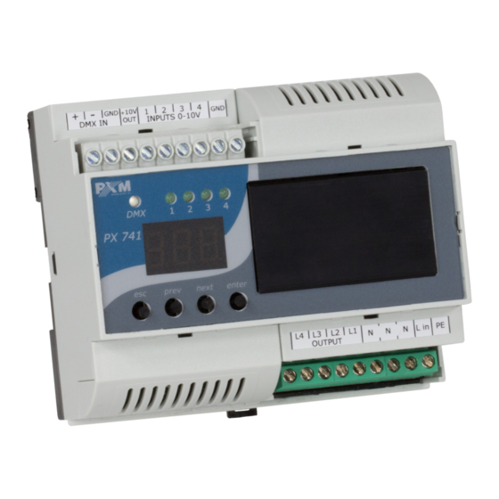
3. DESCRIPTION OF CONNECTORS AND CONTROL ELEMENTS output 10V signal analogue/digital inputs DMX input Supply connector (starting from the left L4, L3, L2, L1, 3xN, Lin and PE) L1-L4 are the output (con- trolled) phases 4. SYMBOLS OF SHOWN MESSAGES address of the DMX device –... - Page 6 reset to factory default settings control source selection control curve selection control range selection setting a linear control curve setting a switched control curve setting a logarithmic control curve setting an exponential control curve with index 2 setting an exponential control curve with index 3 minimum level of an output connection while rising minimum level of an output connection while falling maximum control level...
- Page 7 scene: a control value for no DMX signal first channel total working time of the device total duration of channel control setting seconds setting minutes setting an hour setting a day number setting a year infinity inversion of the selected control curve setting a normal (non-inverted) selected control curve confirmation switching off...
-
Page 8: Device Programming
- enters the next MENU level and confirms changes made 5.2. Setting control modes The menu of the PX741 device allows to set the control mode of the device. Each of the device channels can be controlled with: the DMX dMX signal( Ÿ... -
Page 9: Reaction To The Lack Of The Dmx Signal
5.2.1.2. Reaction to the lack of the DMX signal This function is used both to secure the installation against disappearance of the DMX signal and to achieve the desired value without the connection of an outer controller. On activating it, in case of no DMX signal, the module will realize the selected option individually. -
Page 10: Analogue Control
5.2.2. Analogue control enter enter enter next wciśnięty next enter enter enter enter enter next next next wciśnięty enter enter The control source from the analogue inputs can be set for each channel individually (Ind for the channels CH1 – CH4) or collectively for all of them ALL. Calibration should be carried out to ensure that the inputs work correctly. -
Page 11: Control With Buttons
5.2.3. Control with buttons The control source form the digital inputs (with the buttons) can be set for each channel individually (Ind for the channels CH1 – CH4) or collectively for all of them ALL. The first step is to select one of four functions Fn1 – Fn4 (described on next pages), and then to set its parameters. - Page 12 FUNCTION DIAGRAMS FOR EXTERNAL BUTTON CONTROL Function one output Falling time (parameter dnt) Rise time (parameter uPt) Time Pressing Releasing and holding the key the key down Function two output Falling time (parameter dnt) Rise time (parameter uPt) Time Pressing Short pressing Releasing and holding...
- Page 13 Function three output Rise time Falling time (parameter uPt) (parameter dnt) Time Short pressing (<500 ms) Function four duration (parameter hLd) output Rise time Falling time (parameter uPt) (parameter dnt) Time Short pressing (<500 ms) Each next short pressing of a key when the function realizes the parameter hLd causes that the time of the parameter is counted from 0 (it resets the time elapsed), prolonging the operation of the function at the same time.
-
Page 14: Choice Of The Control Curve
5.3. Choice of the control curve One of five control curves of the output can be selected for each channel: linear ( ) - the value on the output is linearly proportionate to the control value, Ÿ switched ( ) - the two-stage characteristic, Ÿ... -
Page 15: Control Range
5.4. Control range The minimum and maximum control values and the manner of behaviour while reaching the limit values can be defined for each channel: The minimum level of connecting the output while rising ( Ÿ The minimum level of connecting the output while falling ( Ÿ... - Page 16 Below there are exemplary diagrams of control for the linear curve: a) Str = OFF, PrE = On Output 100% The curves: control level value on the output Loä Loæ b) Str = OFF, PrE = OFF Output 100% Loä Loæ...
-
Page 17: Screen Saving
5.5. Screen saving The device was equipped with the possibility to switch off backlights for LED displays and signalising diodes. The activated option bLc switches off the display after a period of one minute of inactivity (when the buttons are not used). The device is still working without interference with other parameters. -
Page 18: Version Of Company Software
5.8. Version of company software To verify the latest version of film software, the option Fir should be selected and then the key "enter" should be pressed to confirm. enter x next enter 5.9. Default settings To restore the factory default values, the dEF option should be selected and the key "enter" should be kept longer. -
Page 19: Rdm
6. RDM The PX741 supports the DMX-RDM protocol. DMX protocol allows only of a one-way data transmission, while its extension the RDM protocol can transmit information in two directions. This makes possible to simultaneously send and receive information, and hence the possibility of monitoring activities of the compatible devices. - Page 20 Parameter name Description setting the rise time for control with the buttons; DIGITAL_RISE_TIME 0x8056 setting from 0 to 24h, in units 100ms setting the duration for control with the buttons; DIGITAL_LAST_TIME 0x8057 setting from 0 to 24h, in units 100ms setting the falling time for control with the buttons;...
-
Page 21: Menu Diagram
enter enter enter enter next next enter enter next next next next next enter next next next next enter next next next next enter next next next next next next enter enter enter enter next next next enter enter next next next next... -
Page 22: Wiring Diagram
8. WIRING DIAGRAM a) DMX Controller controller, e.g PX333 PROTECTIVE STRAND PHASE STRAND Type C circuit breaker, NEUTRAL STRAND 230V POWER SUPPLY... - Page 23 b) Potentiometers control POTENTIOMETERS 0 - 10V IN 0 - 10V IN +10V OUT PROTECTIVE STRAND PHASE STRAND Type C circuit breaker, NEUTRAL STRAND 230V POWER SUPPLY...
- Page 24 c) 0 - 10V control 0 - 10V CONTROL SIGNAL SOURCES 0 - 10V IN 0 - 10V IN 0 - 10V IN 0 - 10V IN PROTECTIVE STRAND PHASE STRAND Type C circuit breaker, NEUTRAL STRAND 230V POWER SUPPLY...
- Page 25 d) Monostable buttons control MONOSTABLE BUTTONS 0 - 10V IN 0 - 10V IN 0 - 10V IN 0 - 10V IN +10V OUT PROTECTIVE STRAND PHASE STRAND Type C circuit breaker, NEUTRAL STRAND 230V POWER SUPPLY...
-
Page 26: Dimensions
9. DIMENSIONS 10. TECHNICAL DATA Type: PX741 Power supply: 230V / 50Hz Max. power consumption: Control inputs: 0 - 10 V or DMX512 or monostable buttons Power consumption inputs 0 - 10V: 0,1mA Dimensions: Width: 105 mm Height: 58 mm... -
Page 27: Declarations Of Conformity
012 385 83 06 http://www.pxm.pl 32-003 Podłęże fax: 012 626 46 94 DECLARATION OF CONFORMITY PXM Marek Żupnik spółka komandytowa Podłęże 654, 32-003 Podłęże declares under our sole responsibility that the product: Name of product: Trailing Edge Dimmer 4 x 200W...
Need help?
Do you have a question about the PX741 and is the answer not in the manual?
Questions and answers