Table of Contents
Advertisement
Quick Links
Advertisement
Table of Contents

Subscribe to Our Youtube Channel
Related Manuals for PXM PX156


Summary of Contents for PXM PX156
- Page 1 PX156 MultiSystem Dimmer 2 x 1200W User manual...
-
Page 2: Table Of Contents
Table of Contents 1 Description....................4 2 Safety conditions..................5 3 Connectors and control elements............7 4 Designation of displayed messages............7 5 Dimmer programming................9 6 Programmable parameters..............9 6.1 Digital input settings....................10 6.1.1 Group parameters.................... 11 6.1.2 Individual parameters..................12 6.1.3 Temperature...................... 13 6.1.4 Input control mode..................13 6.1.5 Scenes and chaser programming..............13 6.2 Analog input settings....................14 6.2.1 Group parameters.................... - Page 3 11.4 Monostable buttons control.................30 12 Dimensions.....................31 13 Notes......................31 14 Technical data..................32 Manufacturer reserves the right to make modifications in order to improve device operation. PXM Marek Żupnik sp.k. Podłęże 654 tel. +48 12 385 83 06 32-003 Podłęże mail: info@pxm.pl Rev.1-6 BDO register number 000005972 www.pxm.pl...
-
Page 4: Description
Description Professional digital dimmer designed for fixed installations. The device depending on the model allow to control four or two independent circuits of 600W or 1200W loads each. It has built-in interference suppression system, signal lights, fuses, DMX-512 control and 0 – 10V input. There are also external control keys available that work in accordance with one of four built-in functions. -
Page 5: Safety Conditions
The control is possible by means of: DMX-512 digital signal, analog signals 0 – 10V or using external keys. Safety conditions PX156 dimmer is powered directly from standard 230V grid, what can cause electric shock when safety rules are not observed. Therefore it is necessary to observe the following: 1. - Page 6 8. After the installation is completed, check the neutralization efficacy of all powered devices. 9. All repairs demanding casing opening should be made with cut off power supply. 10. The device should be strictly protected against water and other liquids. 11.
-
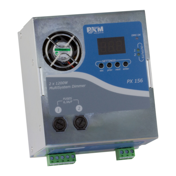
Page 7: Connectors And Control Elements
Connectors and control elements DMX-512 and analog 0 - 10V control inputs Display DMX signal presence LED indicator Output signals presence LED indicators Programming buttons Output fuses Power supply couplings Control outputs Designation of displayed messages No DMX signal: slow dimming of all outputs Minimal brightness of a particular channel show in percentage (%) Maximal brightness of a particular channel show in percentage (%) Limit –... - Page 8 Built-in factory chaser (in addition – reaction to DMX signal loss) Programmable chaser (in addition – reaction to DMX signal loss) Characteristics, 6 different characteristics to choose from Scenes and chasers programming Exponential characteristics F01 – F04, numbers of the edited scenes XFade switching on / off (for scene smooth changing) Analog input 0 –...
-
Page 9: Dimmer Programming
Switching the input mode (digital / analog) External button control Control function executed with external button no. 1 Maximum brightness duration time for button control Temperature sensor fail – contact service for repair Analog mode – selecting this option in the main menu activates analog control mode (also in the noS mode) Dimmer programming After turning the device on, software version is shortly displayed. -
Page 10: Digital Input Settings
2. Individual parameters – Ind – each channel may be set with individual parameters, including individual DMX addressing. The same address may be set to more. Group parameters have a higher priority than individual parameters. This means that programming in the ALL mode, for example, the DMX address, cancels the previous settings for all channels. -
Page 11: Group Parameters
ENTER NEXT NEXT NEXT ENTER NEXT 6.1.1 Group parameters 1. Adr – DMX address from the range 1 to 5011 (setting 5011 as the address for the first channel means automatically address 512 for the second dimmer channel). 2. Cur – characteristic, there are 9 options to choose from: ◦... -
Page 12: Individual Parameters
6. noS – precise the dimmer reaction to DMX signal interruption. There are 11 options to choose from: ◦ On – turning all outputs on at 100% ◦ OFF – turning all outputs off ◦ HLd – the last received value is held ◦... -
Page 13: Temperature
6.1.3 Temperature °C – this parameter allows to check the dimmer internal temperature in the range -40 to +125°C. NOTE! Message Er1 means sensor failure, so service is necessary. 6.1.4 Input control mode AdC – switching between default digital control mode (DMX-512, setting OFF) and analog mode (0 –... -
Page 14: Analog Input Settings
6.2 Analog input settings Analog input from smooth 0 – 10V control or monostable button control is active with the parameter AdC set to On. ENTER NEXT NEXT NEXT ENTER NEXT 6.2.1 Group parameters 1. AIn – detailed settings for analog control input: ◦... -
Page 15: Individual Parameters
◦ Inu – inverted ◦ LnU – logarithmic ◦ E_P – exponential ◦ nE1 … nE3 – for neon lamps control * ◦ Li2 – linear 15 – 100% (zero value at the power output for DMX values of 0 – 15%) 3. -
Page 16: Temperature
◦ E_P – exponential ◦ nE1 … nE3 – for neon lamps control * ◦ Li2 – linear 15 – 100% (zero value at the power output for DMX values 0 – 15%) 3. ACL – limits the output voltage in the range from 50 – 230V 6.2.3 Temperature °C –... -
Page 17: Function Diagrams For External Button Control
6.3 Function diagrams for external button control 6.3.1 Function one (ACL) Rising time (parameter rIS) Button held pressed Button released Time 6.3.2 Function two (ACL) Rising time (parameter rIS) Button held pressed Button released Time Short press (<500 ms) -
Page 18: Function Three
6.3.3 Function three (ACL) Rising time (parameter rIS) Time Short Short Short Short press press press press (<500 ms) (<500 ms) (<500 ms) (<500 ms) 6.3.4 Function four Duration time (parameter LAS) (ACL) Rising Fall down time time = rising time (parameter rIS) Time Short... -
Page 19: Function Five
Each subsequent short press of a key, when the function performs the LAS parameter, causes the parameter time to be counted from 0 (reset the elapsed time). The value of this parameter is taken into account only in the fourth function. The other three are ignored. 6.3.5 Function five (ACL) Button A... -
Page 20: Dimmer Access Lock
NOTE! To use this function additional resistor should be installed before external button “B” (as in the schematic diagram below). REFLECTORS Additional BUTTON A resistor max. 2 x 1200W L OUT 2 BUTTON B N OUT L OUT 1 RCCB with overload type C 10A PHASE STRAND... -
Page 21: Switching The Access Lock On
7.1 Switching the access lock on 1. Press Esc enough times to leave dimmer programming mode – the display will show finally DMX address. Then press and hold Esc and press Next – the display will answer with PAS lettering. Release Esc key. - Page 22 NOTE! Confirming the wrong password will display bAd. Nit is necessary to start unlocking procedure from beginning. The third time wrong password setting lock the dimmer permanently, displaying Loc. The telephone contact to service is necessary to reset the password.
-
Page 23: Menu Scheme For Digital Input
Menu scheme for digital input ENTER ENTER ENTER NEXT NEXT NEXT ENTER ENTER ENTER ENTER NEXT NEXT NEXT NEXT ENTER NEXT NEXT ENTER ENTER NEXT ENTER NEXT PREV NEXT NEXT NEXT NEXT ENTER NEXT NEXT ENTER ENTER ENTER NEXT NEXT NEXT NEXT NEXT... -
Page 24: Menu Scheme For Analog Input
Menu scheme for analog input ENTER ENTER ENTER NEXT NEXT NEXT ENTER ENTER ENTER ENTER ENTER ENTER NEXT NEXT NEXT NEXT NEXT NEXT ENTER ENTER ENTER NEXT ENTER ENTER NEXT NEXT NEXT ENTER NEXT NEXT NEXT NEXT ENTER NEXT ENTER NEXT NEXT NEXT... -
Page 25: Assembly Of The Device
10 Assembly of the device View of the back of the device Movable catch Handle On the back of the device there is a handle with a movable catch, which enables quick and convenient placement of the device on the T35 mounting rail. -
Page 26: Connection Scheme
To remove the device, press it from the top, and then tilt the bottom of the device towards you. Finally, moving the whole device up slightly can be removed. 11 Connection scheme MultiSystem Dimmer must be connected to the DMX line in series. That means, the control cable must be driven to the DMX coupling of the dimmer, and then driven out from the same coupling (refer to the scheme below) to the next DMX-512 signal receivers. -
Page 27: Dmx-512 Signal Control
11.1 DMX-512 signal control DMX CONTROLLER REFLECTORS max. 2 x 1200W DMX- L OUT 2 DMX+ N OUT L OUT 1 RCCB with overload type C 10A PHASE STRAND NEUTRAL STRAND PROTECTIVE STRAND 230V POWER SUPPLY... -
Page 28: Control Of Linear Potentiometers
11.2 Control of linear potentiometers REFLECTORS max. 2 x 1200W 0 - 10V IN 0 - 10V IN L OUT 2 +10V OUT 10kΩ POTENTIOMETERS N OUT L OUT 1 RCCB with overload type C 10A PHASE STRAND NEUTRAL STRAND PROTECTIVE STRAND 230V POWER SUPPLY... -
Page 29: 10V Control
11.3 0 – 10V control REFLECTORS 0 - 10V CONTROL SIGNAL SOURCES max. 2 x 1200W 0 - 10V IN 0 - 10V IN L OUT 2 N OUT L OUT 1 RCCB with overload type C 10A PHASE STRAND NEUTRAL STRAND PROTECTIVE... -
Page 30: Monostable Buttons Control
11.4 Monostable buttons control MONOSTABLE BUTTONS 0 - 10V IN 0 - 10V IN REFLECTORS max. 2 x 1200W L OUT 2 N OUT L OUT 1 RCCB with overload type C 10A PHASE STRAND NEUTRAL STRAND PROTECTIVE STRAND 230V POWER SUPPLY... -
Page 31: Dimensions
12 Dimensions Description of connections 13 Notes * neon lamps control characteristic – each characteristic (nE1, nE2, nE3) is dedicated to inductive load control as for neon lamp transformers. Differences between characteristics are only in lamp switching level, so the start brightness of the lamp. -
Page 32: Technical Data
14 Technical data type PX156 power supply 230V AC max. current consumption digital DMX-512 signal control inputs analog 0 – 10V monostable keys current consumption input 0 – 10V load capacity of the control output +10V out 10mA 60°C – automatic launch of electronically... - Page 33 Podłęże, 20.05.2019 DECLARATION OF CONFORMITY PXM Marek Żupnik spółka komandytowa Podłęże 654, 32-003 Podłęże we declare that our product: Product name: MultiSystem Dimmer 2 x 1200W Product code: PX156 meets the requirements of the following standards, as well as harmonised...
Need help?
Do you have a question about the PX156 and is the answer not in the manual?
Questions and answers