Table of Contents
Advertisement
Quick Links
1. Before You Begin
Ensure the installation of the system meets applicable
state and national electrical code requirements.
The installation of the system should only be
performed by a qualified installer.
When connecting the device to an external power supply,
do not exceed the defined voltage: 9-30 Vdc max.
Contains no user serviceable parts. Unauthorized
modification to device or supplied accessories may
damage devices and void warranty.
This product is NOT intended for use in hazardous locations.
Do NOT install or mount on an application with
high vibration.
The WIO® System must be installed within an
enclosure that requires a tool to access. This is to
prevent inadvertent disconnection of any of the power
wiring, signal wiring or communication cables.
Go to www.wio.oleumtech.com to view or download the
full User Guide for detailed installation and other
helpful information.
support@prosoft-technology.com
www.prosoft-technology.com
1.661.716.5100
2. Required Items
- BR-xxxx-RM4 Radio Kit with Onboard I/O
- (2) 9-30 Vdc power sources
- Technician's screwdriver (flathead)
- (2) 35 mm standard DIN rails (35 x 7.5 mm)
- (2) NEMA 4X-type enclosures for outdoor installation
- (2) antennas (must match system's RF type)
- (2) low loss antenna cables, SMA to N (male)
- (2) low loss antenna cables, N to N (male) (optional)
- (2) lightning arrestors (strongly recommended for outdoors)
- Weatherproofing tape/sealant material
- Wire (solid/stranded AWG 28-12 gauge)
Wireless I/O System - RM4
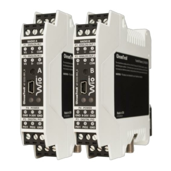
3. Hardware Overview
- Operating temperature range: -40 ˚C to 80 ˚C
RADIO A
RADIO B
P1 - Analog In 1
P2 - Analog In 2
Tx Speed / Reset Button
Mini-USB
Firmware Upgrade
Diagnostic LEDs RF/PIO
P4 - Power 9-30 Vdc
P3 - Digital PIO 1/2
DIP Switches 1-8
DIN Rail Hook
Spring-loaded
Latching Clip
SMA Female
4. RF Transmission (Tx) Speed / Device Reset
1. The system offers two Tx speeds: 1 sec (def.) or 400 ms
Use the Tx button to switch between speeds.
2. Device reset: hold down the Tx button for ~4 seconds until the
LEDs are extinguished. Power cycling will also reset the device.
5. LED Diagnostics
RF
PIO
1. RF Diagnostics
Flashing Green:
Good RF signal: -40 dB (best) to -94 dB
LED flashing speed also indicates
Tx speed.
Flashing Yellow:
Weak RF signal: Worse than -94 dB.
Solid Yellow:
RF failure.
2. Digital PIO Diagnostics
Solid Green:
Indicates both PIO directions are
setup correctly.
Solid Red:
Indicates when one or both PIO
directions are setup incorrectly.
Check PIO DIP switches.
6. Installation
P1 - Analog Out 1
P2 - Analog Out 2
NEMA-Type
Enclosure
P4 - Power 9-30 Vdc
P3 - Digital PIO 1/2
9-30 Vdc
(Reverse polarity protection)
7. RF Best Practices
1. Perform a RF survey prior to installation.
2. Use high quality antennas and low loss cables and fittings
for achieving the best possible wireless performance.
3. Having a clear line of sight between antennas (Fresnel zone)
is ideal for achieving best RF signal quality.
4. When setting up and installing antennas, avoid walls,
tall buildings, trees, and other solid obstructions for
improving RF signal quality.
5. Install antennas at least 10 ft above ground when possible.
6. When using directional antennas, be sure to point the
antennas at each other and be sure to use correct
antenna orientation.
7. Be sure to install omni-directional antennas in vertical position
or perpendicular to the ground.
8. Be sure that there are no loose connections.
Securely tighten all cable connections and wire terminals.
9. Be sure to waterproof all exterior cable connection using high
quality sealing tape.
10. Once the WIO System is up and running, use the left LED
to diagnose RF health.
Quick Start Guide
80-3159-001_C
Install antennas
10 ft above the ground.
Antennas must match
the system's
Radio Frequency (RF).
Directional antennas must be
pointing at each other.
Use low loss antenna
cables and connectors.
Installing lightning
arrestors are strongly
recommended.
Make a hole at the bottom
of the enclosure to run
wires and cables.
Weatherproof all exterior
connections and seal all openings
to the enclosure.
Advertisement
Table of Contents

Related Manuals for OleumTech Wio RM4


Summary of Contents for OleumTech Wio RM4
- Page 1 Spring-loaded wiring, signal wiring or communication cables. Latching Clip 7. RF Best Practices Go to www.wio.oleumtech.com to view or download the full User Guide for detailed installation and other 1. Perform a RF survey prior to installation. SMA Female helpful information.
- Page 2 4-20 mA input module. 7. When the RF communication is lost, the system will ©2019 OleumTech Corporation. All rights reserved. OleumTech and WIO are registered trademarks of OleumTech Corporation in the United States. de-energize the output to notify the change in condition.
Need help?
Do you have a question about the Wio RM4 and is the answer not in the manual?
Questions and answers