
Related Manuals for OleumTech Wio BM-0868-RM1


Summary of Contents for OleumTech Wio BM-0868-RM1
- Page 1 Modular Wireless I/O System User Guide Version 80-7046-001_M Model Numbers RADIO KITS: BM-0868-RM1 | BM-0900-RM1 | BM-0915-RM1 | BM-2400-RM1 I/O MODULES: BM-D100-144 / BM-A420-122 / BM-A010-122...
-
Page 2: Table Of Contents
Modular Wireless I/O System – User Guide CONTENTS PREFACE/SAFETY ........................... 2 COMPLIANCES ............................4 SYSTEM OVERVIEW ..........................5 HARDWARE AT A GLANCE ........................7 INSTALLATION ............................8 RF SETUP – BEST PRACTICE ......................... 13 SIGNAL CHAIN DIAGRAM ........................14 RADIO MODULE WIRING DIAGRAMS ....................15 DIGITAL I/O MODULE WIRING DIAGRAMS .................. -
Page 3: Preface/Safety
This guide also provides how to use the WIO System’s Advanced User Interface. You can also utilize the online video training program available on at http://wio.oleumtech.com as a supplemental learning tool. If you have any questions about this product, you may call or email: ProSoft Technology Support Services 1.661.716.5100... - Page 4 Modular Wireless I/O System – User Guide WARNING: Ensure installation of the system meets applicable state and national electrical code requirements. WARNING: The installation of the system should only be performed by a qualified installer. WARNING: To prevent ignition of flammable or combustible atmospheres, disconnect power before servicing. WARNING: Power must be disconnected or turn off prior to attaching or removing any I/O Modules from the system –...
-
Page 5: Compliances
Modular Wireless I/O System – User Guide 2. COMPLIANCES Important Information to the User This device MUST be professionally installed only by a factory representative or a trained authorized technician. Changes or modifications not expressly approved by the manufacturer may void the user’s authority to operate the equipment. -
Page 6: System Overview
Modular Wireless I/O System – User Guide 3. SYSTEM OVERVIEW SYSTEM HIGHLIGHTS - Point-to-point wireless I/O mirroring system - Replicate raw signals in either direction (bi-directional) - Fully customizable modular I/O solution - Supports 0-10 V, 4-20 mA, and discrete I/O - No software configuration required - Mounts onto a 35 mm DIN rails - Class I, Division 2 (Zone 2) certified... - Page 7 Custom-Tailor I/O Mix, Bi-Directional The OleumTech® WIO® Modular Wireless I/O System provides instant I/O connectivity and is one of the easiest and most cost- effective solutions for solving a vast number of point-to-point I/O and stranded asset monitoring and control challenges. Each Radio Kit can be fully customized using available 0-10 Vdc, 4-20 mA, and Digital I/O Modules.
-
Page 8: Hardware At A Glance
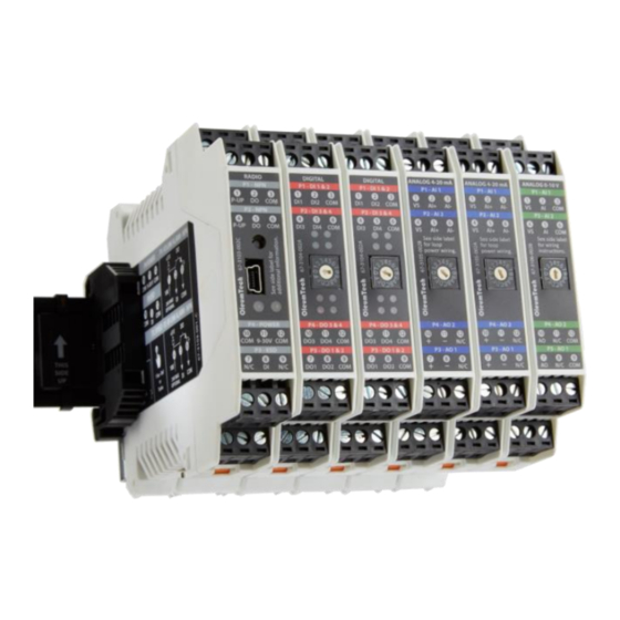
Modular Wireless I/O System – User Guide 4. HARDWARE AT A GLANCE ❹ ❶ ❷ ❸ 1. Radio Module: BM-0868-RM1 (EU), BM-0900-RM1 (NA/ME), BM-0915-RM1 (Aus/NZ), BM-2400- RM1 (NA/ME) a. Radio Module Kit (BM-xxxx-RM1K) 2. Digital Module: BM-D100-144 a. 2-Pack (BM-D100-144D); 1-Pack (BM-D100-144S) 3. -
Page 9: Installation
Modular Wireless I/O System – User Guide 5. INSTALLATION A. Outdoor Enclosure Installation 1. Install or use existing outdoor NEMA-type enclosure. 2. Be sure the WIO® System meets applicable grounding requirements in the enclosure. 3. Install a 35 mm x 7.5 mm DIN rail (at least 166 mm (6.5-inch) wide) inside the enclosure. 4. - Page 10 Modular Wireless I/O System – User Guide B. WIO® System Assembly (attach from left to right) WARNING: Power must be disconnected or turned off prior to attaching or removing any I/O Modules from the system – failure to comply may cause damage hardware. WARNING: Entire system with Radio and I/O Module(s) must be fully assembled before supplying power to the Radio Module for the system to boot and operate properly.
- Page 11 Modular Wireless I/O System – User Guide Connect Antenna. Radio Module is equipped with SMA (female) connector. For outdoor installation, place a lightning arrestor between Antenna and Radio Module connection. Radio Lightning Arrestor Antenna SMA (F) N (Female) N (F) Attach I/O Module(s) to the system.
- Page 12 Modular Wireless I/O System – User Guide Protect any unused DataRail slots with Cover. Snap-off extra pieces and store for future use. Terminate I/O and supply power as required. Use solid or stranded wire (AWG) 28-12.
- Page 13 Modular Wireless I/O System – User Guide C. How to Detach Components from DataRail WARNING: All live wiring connections and power must be safely disconnected before taking any components off the DataRail or WIO® System! AVERTISSEMENT: Tous les branchements et l'alimentation doivent être déconnectés en toute sécurité avant de retirer tout composant du système DataRail ou WIO®! End Terminal Bracket can be removed from din rail by inserting the tip of a flathead screwdriver into the removal slot.
-
Page 14: Rf Setup - Best Practice
Modular Wireless I/O System – User Guide 6. RF SETUP – BEST PRACTICE 1. When setting up and installing antennas, avoid walls, tall buildings, trees, and other solid obstructions for improving RF signal quality. 2. Having a clear line of sight between antennas is ideal for best RF signal quality. 3. -
Page 15: Signal Chain Diagram
Modular Wireless I/O System – User Guide 7. SIGNAL CHAIN DIAGRAM... -
Page 16: Radio Module Wiring Diagrams
Modular Wireless I/O System – User Guide 8. RADIO MODULE WIRING DIAGRAMS A. Radio Module Overview (BM-0900-RM1 Shown) Connect I/O Link Alarm output to report when there is an I/O link failure. Once the failure is corrected, must reset power. Connect RF Link Alarm output to report when there is an RF link... - Page 17 Modular Wireless I/O System – User Guide B. Isolation vs Non-Isolation...
-
Page 18: Digital I/O Module Wiring Diagrams
Modular Wireless I/O System – User Guide 9. DIGITAL I/O MODULE WIRING DIAGRAMS A. Digital Module Overview (BM-D100-144 Shown) See subsection D for LED behaviors. Use Solid / Stranded (AWG) 28-12 Wire Gauge Digital I/O Module does not share a common ground with Radio Module. All inputs and outputs on I/O Modules provide field isolation. - Page 19 Modular Wireless I/O System – User Guide B. Digital Input Wiring...
- Page 20 Modular Wireless I/O System – User Guide C. Digital Output Wiring...
- Page 21 Modular Wireless I/O System – User Guide D. Digital Module Signal Scheme The digital inputs are designed for use with dry contact switches and digital output devices (active low). Vih = 2.34V, Vil = 1.1 V, and Vin = 30 V max LED Behaviors LEDs on this device (both inputs and outputs) are controlled using active low logic.
-
Page 22: Analog 4-20 Ma I/O Module Wiring Diagrams
Modular Wireless I/O System – User Guide 10. ANALOG 4-20 mA I/O MODULE WIRING DIAGRAMS A. 4-20 mA Module Overview (BM-A420-122 Shown) VS/External Power (min) = 10 + Max Current (Amp) * R loop = Total Loop Impedance loop Use Solid / Stranded (AWG) 28-12 Wire Gauge 4-20 mA I/O Module does not share a common ground with Radio Module. - Page 23 Modular Wireless I/O System – User Guide B. 4-20 mA Input Wiring...
- Page 24 Modular Wireless I/O System – User Guide C. 4-20 mA Output Wiring...
-
Page 25: Analog 0-10 V I/O Module Wiring Diagram
Modular Wireless I/O System – User Guide 11. ANALOG 0-10 V I/O MODULE WIRING DIAGRAM A. 0-10 V Module Overview (BM-A010-122 shown) Use Solid / Stranded (AWG) 28-12 Wire Gauge 0-10 V I/O Module does not share a common ground with Radio Module. All inputs and outputs on I/O Modules provide field isolation. -
Page 26: Diagnostics
Modular Wireless I/O System – User Guide 12. DIAGNOSTICS A. Radio Module 1. RF LED (Left): 2. Green: RF traffic / data rate Yellow: RF link failure i. Visual indication of RF link failure after 10 second RF timeout and showing the WIO® System is operating in FailSafe mode. -
Page 27: Advanced User Interface For Pc
WIO. A. Download and Install Software a. Click here to download the latest version of the software or go to the web site http://wio.oleumtech.com b. Install Software on Windows®-based PC. i. Follow the On-Screen Setup Guide. - Page 28 Modular Wireless I/O System – User Guide C. View of Graphic User Interface (GUI) a. OFF – When PC is not connected to a Radio Module, all gauges and controls are disabled. b. ON - When PC is connected to a Radio Module (powered on), all gauges and controls will be enabled.
- Page 29 Modular Wireless I/O System – User Guide D. Main Window Guide ❶ ❸ ❷ ❹ ❺ ❻ ❼ ⓫ ❽ ❾ ❿ Screen Size – Zoom In/Out Local RSSI (Received Signal Strength Indicator) This level indicates the incoming signal strength received from remote Radio. Remote RSSI This level indicates the outgoing signal strength from local Radio to remote Radio.
- Page 30 Modular Wireless I/O System – User Guide E. Additional Diagnostics ❷ ❶ ❸ 1. RF Link Failure Indicator The RF Link Fail Output (NPN) on Radio Module also triggered when failure occurs. 2. I/O Link Failure Indicator The I/O Link Fail Output (NPN) on Radio Module also triggered when failure occurs. 3.
- Page 31 Modular Wireless I/O System – User Guide F. Digital Module Window Guide ❶ ❷ ❹ ❸ ❺ ❻ ❼ ❽ 1. Digital Input(s) Status: Green – On ; Dimmed - Off 2. Digital Output(s) Status 3. Red LED: displayed when output is normally operated; Dimmed - Off 4.
- Page 32 Modular Wireless I/O System – User Guide G. 4-20 mA Module Window Guide ❶ ❷ ❸ ❹ ❺ ❻ ❼ ❽ ❾ Input 1 Status Input 2 Status Output 1 Status (Red Needle) Output 2 Status (Red Needle) FailSafe Without the User Interface (default), the output reports last known value when RF or I/O failure occurs. Press “Fs”...
- Page 33 Modular Wireless I/O System – User Guide H. 0-10 V Module Window Guide ❶ ❷ ❸ ❹ ❺ ❻ ❼ ❽ ❾ Input 1 Status Input 2 Status Output 1 Status (Red Needle) Output 2 Status (Red Needle) FailSafe Without the User Interface (default), the output reports last known value when RF or I/O failure occurs. Press “Fs”...
-
Page 34: Specifications
Modular Wireless I/O System – User Guide 14. SPECIFICATIONS A. HARWARE AND SYSTEM Unique System Features Bi-Directional, Paired, Wireless I/O Communication System No Software or Programming Required Maximum Network Capacity Max Capacity Depends on I/O Combination Impacting Power When Using More Than 5 Modules Use Power Budget Calculator http://goo.gl/t67r3k DIN Rail Mounting Compatibility 35 mm x 7.5 mm DIN Rail... - Page 35 Modular Wireless I/O System – User Guide B. SAFETY AND COMPLIANCE Operational Temperature -40 °C to 80 °C / -40 °F to 176 °F Ambient Temperature -20 °C to 80 °C / -4 °F to 176 °F Humidity 0 to 99 %, Non-condensing Degree of Protection IP20 / Plastic Hazardous Locations Classifications...
- Page 36 Modular Wireless I/O System – User Guide C. RADIO MODULE Frequency 868-870 MHz | 902-928 MHz | 915-928 MHz |2.4 GHz Antenna Connector Type SMA (Female Connector) Default Transmit Speed / Update 1 Second Turbo Tx Speed Based on 1=100 ms, 2-3=200 ms, 4= 250 ms, 5-6=333 ms, Number of I/O Modules 7-11=500 ms, 12-16=1 second Outdoor / Line of Sight Max Range...
- Page 37 Modular Wireless I/O System – User Guide D. DIGITAL I/O MODULE Number of Inputs Number of Outputs Input Voltage Range 3-30 Vdc Isolation Voltage 2500 V r.m.s. Input Voltage Threshold Signal ("H"): > 2.3 Vdc 0 Signal ("L"): < 1.1 Vdc Output Rating 1 A Sink Current for Open-Drain Outputs / NPN...
- Page 38 Modular Wireless I/O System – User Guide F. 0-10 V I/O MODULE Number of Inputs 2 (24-bit Resolution) Number of Outputs 2 (16-bit Resolution) Signal Range 0 Vdc to 10 Vdc (10.5 V Max) Isolation Voltage 2500 V r.m.s. Accuracy <...
-
Page 39: Frequently Asked Questions (Faqs)
The Radios come paired and secured and is meant for point-to-point applications only. For more advanced networking solutions, OleumTech offers a different, more advanced wireless sensor network for setting up a sophisticated network that can handle point-to-point, point-to-multipoint, and peer-to-peer. - Page 40 23. How can I obtain tech support or RMA? Please email us at techsupport@oleumtech.com or give us a call to begin the service process. You will be guided by our helpful customer service staff member to help you get through any issue you are having with the WIO...
-
Page 41: Warranty
OleumTech warrants that goods repaired by it pursuant to the warranty are free from defects in material and workmanship for a period to the end of the original warranty or ninety (90) days from the date of delivery of repaired goods, whichever is longer. -
Page 42: Revision History
Modular Wireless I/O System – User Guide 17. REVISION HISTORY Rev. A: Original Release Rev. B: Added loop power wiring diagram for 4-20 mA I/O Module. Added Power Budget Calculator hyperlink. Rev. C: Updated system overview. Updated product technical specifications including power consumption. Rev. - Page 43 OleumTech has made a good faith effort to ensure the accuracy of the information in this document and disclaims the implied warranties of merchantability and fitness for a particular purpose and makes no express warranties, except as may be stated in its written agreement with and for its customers.
Need help?
Do you have a question about the Wio BM-0868-RM1 and is the answer not in the manual?
Questions and answers