
Related Manuals for OleumTech Wio BR-0900-RM4


Summary of Contents for OleumTech Wio BR-0900-RM4
- Page 1 Radio Kit with Onboard I/O User Guide Version 80-7059-001_E Model Numbers BR-0900-RM4 | BR-0915-RM4 | BR-2400-RM4...
-
Page 2: Table Of Contents
Radio Kit with Onboard I/O – User Guide CONTENTS PREFACE/SAFETY ........................... 2 SAFETY AND COMPLIANCE ........................3 SYSTEM OVERVIEW ..........................4 SIGNAL CHAIN DIAGRAM ........................5 HARDWARE AT A GLANCE ........................6 RF DIAGNOSTICS AND TRANSMISSION SPEED ..................7 DIP SWITCH FUNCTIONS ........................8 RF SETUP –... -
Page 3: Preface/Safety
PREFACE/SAFETY Thank you for choosing the WIO ® System - Radio Kit with Onboard I/O by OleumTech ® In order to make the most of the advanced features and performance provided by this wireless I/O system, please read this user guide thoroughly before using the system. -
Page 4: Safety And Compliance
Radio Kit with Onboard I/O – User Guide SAFETY AND COMPLIANCE Important Information to the User This device MUST be professionally installed only by a factory representative or a trained authorized • technician. Changes or modifications not expressly approved by the manufacturer may void the user’s authority to •... -
Page 5: System Overview
• Integrated Radio and I/O Design The OleumTech® WIO® Radio Kit with Onboard I/O provides instant I/O connectivity and is one of the easiest and most cost-effective solutions for solving a vast number of point-to-point I/O and stranded asset monitoring and control challenges. The kit is comprised of Radio Modules A and B. -
Page 6: Signal Chain Diagram
Radio Kit with Onboard I/O – User Guide SIGNAL CHAIN DIAGRAM A. Analog 4-20 mA Analog signals travel only in one direction from Radio A to Radio B. B. Digital/Discrete Programmable I/O (PIO) The direction of digital signals are programmable by channel, meaning they can travel in either direction based on DIP switch configuration: Radio A to B or Radio B to A. -
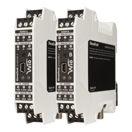
Page 7: Hardware At A Glance
Radio Kit with Onboard I/O – User Guide HARDWARE AT A GLANCE... -
Page 8: Rf Diagnostics And Transmission Speed
Radio Kit with Onboard I/O – User Guide RF DIAGNOSTICS AND TRANSMISSION SPEED A. RF Diagnostics RF health can easily be diagnosed using the left LED located on the front panel. i. Be sure both antennas are installed properly and connected securely to the Radio Modules. -
Page 9: Dip Switch Functions
Radio Kit with Onboard I/O – User Guide DIP SWITCH FUNCTIONS Device must be reset or power-cycled after modifying any DIP switch settings. L'appareil doit être réinitialisé ou redémarré après avoir modifié les paramètres du commutateur DIP. DIP Switches 1 to 8 (left to right) A. - Page 10 Radio Kit with Onboard I/O – User Guide B. Digital Output Fail Safe Modes / RF Health Detection Controlled by DIP Switch 3 i. DIP Switch controls fail over operation for both PIO 1 and 2. When Radio communication is lost for 10 seconds or more, the Radio Module will automatically place the outputs to user-configured fail safe states.
- Page 11 Radio Kit with Onboard I/O – User Guide C. Analog Output Fail Safe Modes Radio B only: Controlled by DIP Switches 4 and 5. When Radio communication is lost for 10 seconds or more, the Radio Module will automatically place the outputs to user-configured fail safe values. RADIO B Examples of fail safe configurations based on DIP switch positions.
- Page 12 Radio Kit with Onboard I/O – User Guide D. RF Transmit Power (900 MHz Only) 900 MHz only: Controlled by DIP Switch 6. 140 mW (default) or 1 W option. Transmit power setting must match on both Radio Modules. RADIO A RADIO B 2.4 GHz system’s transmit power is fixed at 63 mW.
- Page 13 Radio Kit with Onboard I/O – User Guide Radio channel pattern MUST MATCH on both Radio Modules. 900 MHz: controlled by DIP Switches 7 and 8 (channels 0 to 3). RADIO A RADIO B 2.4 GHz: controlled by DIP Switches 6, 7 and 8 (channels 0 to 7) RADIO A RADIO B Examples of how to select RF channel/pattern (2.4 GHZ shown) –...
-
Page 14: Rf Setup - Best Practices
Radio Kit with Onboard I/O – User Guide RF SETUP – BEST PRACTICES Perform a RF survey prior to installation. Use high quality antennas and low loss cables and fittings for achieving the best possible wireless performance. Having a clear line of sight between antennas (Fresnel zone) is ideal for achieving best RF signal quality. -
Page 15: Installation
Radio Kit with Onboard I/O – User Guide INSTALLATION A. Outdoor Installation Install or use existing NEMA-type enclosure. Be sure the WIO® System meets applicable grounding requirements in the enclosure. Install a 35 mm x 7.5 mm DIN rail inside the enclosure. Mount WIO Radio Module onto the DIN rail. - Page 16 Radio Kit with Onboard I/O – User Guide B. How to Detach Radio Module from DIN Rail Radio Module can be removed from the din rail by inserting the tip of a flathead ® screwdriver into removal slot located on the metal latching clip.
-
Page 17: Wiring Diagram
Radio Kit with Onboard I/O – User Guide WIRING DIAGRAM A. Power Wiring: 9-30 Vdc (reverse polarity protection) 1. To reset the device, you can power cycle the device or press and hold Tx button down for ~4 seconds until the LEDs are extinguished. 2. - Page 18 Radio Kit with Onboard I/O – User Guide B. Analog 4-20 mA Input (Radio A only)
- Page 19 Radio Kit with Onboard I/O – User Guide C. Analog 4-20 mA Output Wiring (Radio B only)
- Page 20 Radio Kit with Onboard I/O – User Guide D. Digital/Discrete Input Wiring 1. The PIO DIP switch must be set to Input. Accepts Dry Contact (Internal 3.3 Vdc Pull-Up), Open-Drain (NPN) and Voltage Level Output (0-30 Vdc Max.) Input Voltage Threshold: Signal "H", Vi >...
- Page 21 Radio Kit with Onboard I/O – User Guide 2. Digital/Discrete Output Wiring i. The PIO DIP switch must be set to Output. Open Drain (NPN) Outputs: Inductive Load (Sink Current): 1 Amp/30 Vdc Max. Voltage Level Output: Internal Pull-Up: Signal "H", Vo = 3.3 Vdc Signal "L", Vo = 0.2 Vdc Accepts Optional External Pull-Up, 30 Vdc Max.
-
Page 22: Specifications
Radio Kit with Onboard I/O – User Guide SPECIFICATIONS A. I/O and Hardware Features Analog 4-20 mA Communication Uni-Directional (Radio A to B Only) Digital/Discrete Communication Bi-Directional (Configurable Using DIP Switches) DIO Mismatch Indication - Right LED Green = OK / Red = Mismatch DIN Rail Mounting Compatibility 35 mm Standard DIN Rail (Direct Mount) Built-In Mounting Hardware... - Page 23 Radio Kit with Onboard I/O – User Guide C. Analog Inputs (Radio A Only) 2x Analog Inputs 4 mA to 20 mA (16-bit Resolution) Accuracy < 0.2 % of Full Scale Internal Loop Power 9-30 Vdc AI Input Impedance (loop) 250 Ohm D.
-
Page 24: Conditions Of Acceptability
Radio Kit with Onboard I/O – User Guide CONDITIONS OF ACCEPTABILITY Equipment is only to be installed by manufacturer trained personnel. If at any time there is a conflict between the system safety provisions and any relevant local (national or regional) requirements, the local requirements always take precedence. This product is NOT intended for use in hazardous locations. -
Page 25: Warranty
OleumTech warrants that goods repaired by it pursuant to the warranty are free from defects in material and workmanship for a period to the end of the original warranty or ninety (90) days from the date of delivery of repaired goods, whichever is longer. -
Page 26: Revision History
OleumTech has made a good faith effort to ensure the accuracy of the information in this document and disclaims the implied warranties of merchantability and fitness for a particular purpose and makes no express warranties, except as may be stated in its written agreement with and for its customers.
Need help?
Do you have a question about the Wio BR-0900-RM4 and is the answer not in the manual?
Questions and answers