
Related Manuals for MEN G25A


Summary of Contents for MEN G25A
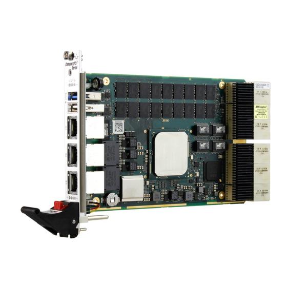
- Page 1 20G025A00 E3 2017-04-20 G25A Intel Xeon D CPU Board 3U CompactPCI Serial User Manual...
-
Page 2: Table Of Contents
Using the G25A under Windows........ - Page 3 3.14.2 Using the G25A as a Peripheral Board ..... . . 50 4 UEFI Firmware ..........51 Accessing the Firmware .
- Page 4 Position of lithium battery on G25A ........
- Page 5 Contents Table 44. BMC API – Software reset commands....... . . 71 Table 45.
-
Page 6: About This Document
This user manual is intended only for system developers and integrators, it is not intended for end users. It describes the design, functions and connection of the product. The manual does not include detailed information on individual components (data sheets etc.). G25A product page with up-to-date information and downloads: www.men.de/products/g25a/ History Issue... - Page 7 About this Document Conventions Indicates important information or warnings concerning situations which could result in personal injury, or damage or destruction of the component. Indicates important information concerning electrostatic discharge which could result in damage or destruction of the component. Indicates important information or warnings concerning proper functionality of the product described in this document.
-
Page 8: Product Safety
Only store the product in its original ESD-protected packaging. Retain the original packaging in case you need to return the product to MEN for repair. 20G025A00 E3 2017-04-20 Page 8 ... -
Page 9: Legal Information
THE IMPLIED WARRANTIES OF MERCHANTABILITY AND FITNESS FOR A PARTICULAR PURPOSE OR USE. In no event shall MEN be liable for more than the contract price for the products in question. If buyer does not notify MEN in writing within the foregoing warranty period, MEN shall have no liability or obligation to buyer hereunder. - Page 10 Legal Information Conformity MEN products are no ready-made products for end users. They are tested according to the standards given in the Technical Data and thus enable you to achieve certification of the product according to the standards applicable in your field of application.
-
Page 11: Product Overview
DIN, EN or IEC industry standards. The G25A is also ready for coating so that it can be used in humid and dusty environments and has a guaranteed minimum standard availability of 7 years. -
Page 12: External Interfaces
Product Overview External Interfaces Figure 1. Front interfaces - G25A 02G025A00 02G025A01 02G025A02 ® ® ® CompactPCI CompactPCI CompactPCI Serial Serial Serial USB 3.0 USB-to-UART Gb Ethernet (X1) 10 Gb Ethernet (X2) 10 Gb Ethernet (X3) G25A G25A G25A 20G025A00 E3... -
Page 13: Figure 2. Front Interfaces - G25A Combined With G229 Peripheral Board
Product Overview Figure 2. Front interfaces – G25A combined with G229 peripheral board Up to 5 UART interfaces: X4: RS232 or RS422/485 (UART2) X5: RS232 or RS422/485 (UART3) X6: RS232 or RS422/485 (UART4) or VGA X7: RS232 (UART0) X8: RS422/485 (UART1) USB 3.0... -
Page 14: Board Layout
Product Overview Board Layout Figure 3. Board layout – top view Heat sink USB 3.0 connector USB-to-UART connector Gb Ethernet connector X1 10 Gb Ethernet connector X2 10 Gb Ethernet connector X3 Op onal ba ery (under the heat sink) Figure 4. -
Page 15: Block Diagram
Product Overview Block Diagram Figure 5. Block diagram - standard G25A ECC DDR4 SDRAM Gb Ethernet CPCI‐ PCIe 2.0 x2 Ethernet ECC DDR4 Controller SDRAM SATA (6 Gb) SMLINK Gb Ethernet (PCIe x1) USB 3.0 10 Gb Ethernet PCIe 3.0 x8 10 Gb Ethernet CPCI‐ PCIe 3.0 x4 Intel Xeon D SoC P1‐P5 PCIe 2.0 x1 UART USB 2.0 UART‐to‐USB SFF‐8485 SGPIO FPGA USB 3.0... -
Page 16: Figure 6. Block Diagram - G25A Combined With G229 Peripheral Board
Product Overview Figure 6. Block diagram - G25A combined with G229 peripheral board RS232 (X7,UART0) RS422/485 (X8, UART1) RS232 or RS422/485 (X4, UART2) FPGA RS232 or RS422/485 mSATA (X5, UART3) PCIe x1 RS232 or RS422/485 (X6, UART4) PCIe x1 PCIe x2 PCI Express Mini PCI Express Switch Card USB 2.0 USB 3.0 PCIe x1 USB 3.0 PCIe x1 USB Controller USB 3.0 F Front... -
Page 17: Technical Data
Product Overview Technical Data The following CPU types are available: Intel Xeon D-1539, 8 Cores Intel Xeon D-1577, 16 Cores Intel Pentium D-1519, Quad Core Intel Virtualization Technology (Intel VT) VT-d VT-x Intel Turbo Boost Technology Intel Hyper-Threading Technology ... - Page 18 Up to three interfaces via SA-Adapters: RS232, not optically isolated, -40..+85°C screened, conformal coating RS232, optically isolated, -40..+85°C screened, conformal coating RS422/485, full duplex, optically isolated, -50..+85°C screened, conformal coating Please contact MEN sales for ordering information. Supervision and Control Board controller Watchdog timer ...
- Page 19 Depends on system configuration (CPU, hard disk, heat sink...) Temperature range (storage): -40°C to +85°C Cooling concept Air-cooled, airflow 1.5 m/s Conduction-cooled in MEN CCA frame Humidity: EN 60068-2-30, EN 50155 Altitude: -300 m to +2000 m Shock: EN 50155 category 1 class B ...
-
Page 20: Product Identification
Product Identification MEN documentation may describe several different models and design revisions of the G25A. You can find the article number, design revision and serial number affixed to the G25A. Article number: Indicates the product family and model. This is also MEN’s main ... -
Page 21: Getting Started
The following steps are necessary: » Power down your system and remove the G25A from the system. » Put the board on a flat surface. » Insert the microSD card into the slot with the contacts at the top. -
Page 22: Connecting And Starting
Remove all boards from the CompactPCI Serial system. » Insert the G25A into the system slot of your system, making sure that the backplane connectors are properly aligned. Note: The system slot of every system is marked by a triangle with a plus sign behind it on the backplane and/or at the front panel: It also has red guide rails. -
Page 23: Troubleshooting At Start-Up
Getting Started Troubleshooting at Start-up If you have any problems at start-up of the G25A, you can check if the front-panel status LED gives an error flash code. Chapter 3.3.3 Status LEDs on page You can also start the board with firmware default settings for troubleshooting. -
Page 24: Using The G25A Under Windows
Getting Started Using the G25A under Windows This chapter describes how to use Windows software together with the G25A. A detailed step-by-step description is given where needed. 2.6.1 Accessing SMBus/I2C Devices MEN provides the Windows ERTC/SMB Support Package (13Y021-70) for accessing SMBus devices, e.g., board management functions. -
Page 25: Configuring The Uart Interfaces
MEN’s driver installation package (Installset) for Windows (13F215-77) allows easy configuration through the Device Manager. To do this, open the Properties page of each G25A UART device via the Windows Device Manager and select the Port Interface tab. See the MEN website for the Windows Installset and user manual: www.men.de/software/13f215-77/... -
Page 26: Using The G25A Under Linux
Getting Started Using the G25A under Linux This chapter describes how to use Linux software together with the G25A. A detailed step-by-step description is given where needed. 2.7.1 Accessing Board Management Functions There are two ways to access board management functions, e.g., the board management controller (BMC), under Linux: Using MEN software tools for Linux. - Page 27 RESET_IN mode get hardware variant ID exit QM-Mode (for production tests only) (c) 2008 by MEN mikro elektronik GmbH » For example, if you want to look up the voltage values, use the following command: sudo xm01bc_ctrl -v xm01bc_1...
- Page 28 Getting Started 2.7.1.2 Standard Linux I2C Tools Carry out the following steps to access the BMC. This procedure is also applicable to other SMBus devices. » Find out the number of the SMBus the BMC is located on by listing the I2C devices: (small l not number 1) sudo i2cdetect -l [...]...
-
Page 29: Managing Rtc Time Adjustments
The ERTC time will not be updated and is out of date. During the next system boot, the OS would use the outdated time. MEN provides a dedicated ERTC driver to manage system time adjustments. See the MEN website for the Application Note "Using the System RTC... -
Page 30: Configuring The Uart Interfaces
Getting Started 2.7.3 Configuring the UART Interfaces MEN provides a Linux driver that allows to configure the interface mode and baud rate.It is included in the 13MD05-90 MDIS5 system package for Linux. See the MEN website for the MDIS system package: www.men.de/software/13md05-90/... - Page 31 Getting Started 2.7.4.1 MEN Tool The MEN MDIS tool provided to access SMBus devices is called smb2_ctrl (MEN article number 13Y004-06). See the HTML documentation included with the tool in the MDIS5 framework for a detailed description. For example, to enable the locate LED of drive 0: sudo smb2_ctrl smb2_2 wbd -a=0xe0 -o=0x00 -d=0x40 2.7.4.2...
-
Page 32: Functional Description
Functional Description Functional Description Power Supply The G25A board is supplied with +12V only. The voltage range is +9.5 V up to +15.5 V (absolute maximum voltage). The voltage is monitored within these limits. Processor Core The following CPU types are available: Table 1. -
Page 33: Supervision And Management
100-ms steps from 100 ms up to 1:49:10 (hh:mm:ss) - 65536 steps. 3.3.2 Temperature Measurement The G25A uses a temperature device to measure the local CPU board temperature. The temperature device is connected to the BMC via I2C, and is supported by the firmware. 20G025A00 E3... -
Page 34: Status Leds
Functional Description 3.3.3 Status LEDs The G25A has two general status LEDs at the front panel which are controlled by the board controller using SMBus commands. Table 2. General status LEDs at front panel CompactPCI CompactPCI CompactPCI Appearance Label Color... - Page 35 Supervision and management functions are accessible by software. Chapter 2.6.1 Accessing SMBus/I2C Devices on page 24 Chapter 2.7.1 Accessing Board Management Functions on page 26 for details on using MEN driver software. Chapter 5.4 BMC API (Application Programming Interface) on page 62 for a ...
-
Page 36: Reset
Functional Description Reset The G25A is equipped with a reset button which is recessed within the front panel and requires a tool, e.g. paper clip to be pressed, preventing the button from being inadvertently activated. Real-Time Clock (RTC) The G25A includes a real-time clock connected to the processor as the system RTC (ERTC) RX-8571. -
Page 37: Memory
See the MEN website for available standard configurations: www.men.de/products/g25a/#ord 3.7.2 Boot Flash The G25A provides 16 MB boot Flash memory. It contains the UEFI firmware and the Intel Management Engine firmware. Mass Storage 3.8.1 microSD Card Slot Within its housing, the G25A provides one microSD card slot. -
Page 38: Serial Ata (Sata)
interfaces in a CompactPCI Serial system. 3.8.2.3 Using the G25A in a CompactPCI Serial Peripheral Slot If the G25A is used in a peripheral slot, the interfaces on the CompactPCI Serial connectors are switched off. 20G025A00 E3 2017-04-20 Page 38... -
Page 39: Usb
ports in a CompactPCI Serial system. 3.9.2.1 Using the G25A in a Peripheral Slot If the G25A is used in a peripheral slot, the USB interface on the CompactPCI Serial connectors is switched off. 20G025A00 E3 2017-04-20 Page 39... -
Page 40: Usb-To-Uart Interface
UART port. The interface supports: Data rates up to 4 Mbit/s 512-byte transmit buffer 512-byte receive buffer See the MEN website for a service cable for USB: www.men.de/products/g25a/#ord 20G025A00 E3 2017-04-20 Page 40 ... -
Page 41: Ethernet
Intel X557 Dual PHY Gigabit Ethernet interfaces: Gigabit Ethernet MAC integrated in the SOC combined with an Intel I218LM Note: The 10 Gigabit interfaces (10GBASE-T) of the G25A do not support Fast Ethernet interfaces (10/100BASE-T). Supported cable lengths: 1 Gigabit Ethernet interfaces: ... -
Page 42: Rear Connection
Functional Description 3.10.1.2 Table 10. Connector types – Ethernet M12 Connector Type On G25A 8-pin M12 receptacle X-coded, e.g., Phoenix Contact SACC-CI-M12FSX- 8CON-L90 Mating 8-pin M12 plug X-coded Table 11. Pin assignment – Ethernet (8-pin M12) 10GBASE-T/ 1000BASE-T BI_DA+ BI_DA-... -
Page 43: Ethernet Mac Addresses
0x 00 C0 3A D0 E0 00 Serial backplane "00 C0 3A" is the MEN vendor code. The last six digits form the unique MAC address for each board. The serial number is added by the last three digits in the range: Serial number 42 (X1): 0x8000 + 0x002A = 0x802A. -
Page 44: Ethernet Status Leds
Functional Description 3.10.5 Ethernet Status LEDs Chapter 1.2 External Interfaces on page 12 for the position of the LEDs. Table 14. Ethernet status LEDs at front panel Appearance Label Color Function CompactPCI CompactPCI CompactPCI Yellow Activity LED On: Tx/Rx activity ... -
Page 45: Rs232 (On G229 Peripheral Board)
RS232 (on G229 Peripheral Board) Table 15. Connector types – 9-pin D-Sub plug Connector Type On G25A 9-pin D-Sub plug according to DIN41652/MIL-C-24308, with thread bolt UNC4-40 Mating 9-pin D-Sub receptacle according to DIN41652/MIL-C-24308, available for ribbon cable (insulation piercing connection), hand-soldering connection or crimp connection Table 16. -
Page 46: Rs422/485 (On G229 Peripheral Board)
RS422/485 (on G229 Peripheral Board) Table 18. Connector types – 9-pin D-Sub receptacle Connector Type On G25A 9-pin D-Sub receptacle according to DIN41652/MIL-C-24308, with thread bolt UNC4-40 Mating 9-pin D-Sub plug according to DIN41652/MIL-C-24308, available for ribbon cable (insulation piercing connection), hand-soldering connection or crimp connection 3.12.1... -
Page 47: Pci Express
PCI Express ports on the rear I/O connectors. See Chapter 3.14 CompactPCI Serial on page If the G25A is used in a peripheral slot, the interfaces on the CompactPCI Serial connectors are switched off. Connection of Gigabit Ethernet controller The controller for the four Gigabit Ethernet channels at the rear is permanently connected via one PCIe 2.0 x2 link. -
Page 48: Compactpci Serial
Functional Description 3.14 CompactPCI Serial Refer to the CompactPCI Serial standard PICMG CPCI-S.0 for detailed information regarding the rear I/O connectors. CompactPCI Serial Specification PICMG CPCI-S.0 Revision 2.0: 2015; PCI Industrial Computers Manufacturers Group (PICMG) www.picmg.org Introduction to CompactPCI Serial on Wikipedia: ... -
Page 49: Table 22. Compactpci Serial Backplane Filling Order
Slot 1 Slot 4 Slot 5 Slot 6 Slot 7 Slot 8 Slot 9 Slot 2 Slot 3 PCI Express Ethernet SATA Implementation on the G25A Express Express Express Express Express Express Express Express 3.0 x8 3.0 x8 3.0 x4 3.0 x4 2.0 x1... -
Page 50: Using The G25A As A Peripheral Board
3.14.2 Using the G25A as a Peripheral Board It is possible to use more than one G25A board within a CPCI-S.0 system to build a redundant system or a cluster with more processing power. The communication between the boards is done via Ethernet in this case and the other high-speed interfaces cannot be used. -
Page 51: Uefi Firmware
The mode can be switched under the MEN tab. Chapter 4.3.2 MEN Menu on page When accessing the G25A via a serial console only the <Esc> key can be used. 20G025A00 E3 2017-04-20 Page 51 ... -
Page 52: Main Menu
In the Main menu you can look up system parameters and set system language, date and time. 4.3.2 MEN Menu The MEN menu has been adapted in order to simplify access to important functions. You can find information regarding board name, board revision and serial number as well as several sub-menus. 20G025A00 E3... -
Page 53: Table 23. Functions In The Men Menu
USB Boot Enabled Disabled 4.3.2.2 MEN Menu – Sub-Menu BMC Settings In the sub-menu BMC Settings you can find board information that is read out via the Board Management Controller (BMC), as well as the following sub-functions: Table 24. Sub-menu BMC Settings... -
Page 54: Table 25. Sub-Menu Network Settings
UEFI Firmware 4.3.2.3 MEN Menu – Sub-Menu Network Settings In the sub-menu Network Settings you can activate and deactivate the Ethernet controllers and the PXE boot functionality. Table 25. Sub-Menu Network Settings Sub-menu Function Options MEN Network Settings Front X1 - 1x 1GbE... -
Page 55: Advanced Menu
UEFI Firmware 4.3.2.5 MEN Menu – Sub-Menu SATA Settings In the sub-menu SATA Settings you can set SATA speed and enable the SGPIO interface. Table 27. Sub-Menu SATA Settings Sub-menu Function Options MEN SATA Settings SATA Speed Limit Unlimited Gen3... -
Page 56: Intelrcsetup Menu
UEFI Firmware 4.3.4 IntelRCSetup Menu Most of the functions in this menu normally do not have to be changed during operation. If you use a RAID in your system, however, some settings have to be made here.. Setting items on this screen to incorrect values can lead to malfunction of the system. -
Page 57: Table 29. Security Modes
UEFI Firmware Table 28. Setting passwords Function Description Administrator Password Sets, changes or deletes the administrator password. If an administrator password is set the systems asks for this first. For deleting the password enter nothing and press the enter key. For entering a new password enter it twice and press the enter key. -
Page 58: Boot Menu
UEFI Firmware 4.3.6 Boot Menu In the boot menu you can make settings regarding boot behavior and boot order. 4.3.7 Save and Exit Menu In the Save and Exit menu you can set how to handle changes made within the setup and exit the setup. -
Page 59: Hardware/Software Interface
Hardware/Software Interface Hardware/Software Interface This chapter is intended for software developers or board integrators who need deeper knowledge of the implementation details of the G25A interfaces and its internal connections. PCI Express Root Port Interrupt Mapping Table 30. PCI Express Root Port Interrupt Mapping for Downstream Devices... -
Page 60: Sata Sgpio Fpga
Hardware/Software Interface SATA SGPIO FPGA Table 32. SMBus/IC2 – SATA SGPIO FPGA – address map Address Offset Register SATA0 Register (SATA drive 0) 0x00 SATA1 Register (SATA drive 1) 0x01 SATA2 Register (SATA drive 2) 0x02 SATA3 Register (SATA drive 3) 0x03 SATA4 Register (SATA drive 4) 0x04... -
Page 61: Table 35. Smbus/Ic2 - Sata Sgpio Fpga - Handle State Register (0Xff)
Hardware/Software Interface Bit Field Description SATA_DETECT Enable or disable passing output pins HANDLE_STATE to the CPU 0: Disable all HANDLE_STATE pins 1: Enable HANDLE_STATE pins SMBALERT_EN Enable or disable passing output interrupt I2C_IRQ_N to the CPU 0: Disable passing SMBALERT interrupt ... -
Page 62: Bmc Api (Application Programming Interface)
Hardware/Software Interface BMC API (Application Programming Interface) The G25A uses a generic command interface for communication between the CPU (host) and the BMC. Application software uses command packets to communicate with the BMC. The application software controls the BMC via I2C/SMBus. The device address is 0x4D (in 7-bit, non-shifted notation) or 0x9A/0x9B (in 8-bit, shifted notation, write/read). - Page 63 Hardware/Software Interface The packet types are directly mapped to the corresponding SMBus “bus protocols” as defined in the System Management Bus Specification. Table 37. BMC API – Packet types mapping on SMBus Packet Type SMBus Protocol PT_SB Send byte PT_RBD Read byte PT_WBD Write byte...
- Page 64 Hardware/Software Interface Commands WDOG_TIME_SET and WDOG_TIME_GET Command WDOG_TIME_SET Opcode: 0x14 Packet Type: PT_WWD Data 0 WD_TOUT (LSB) Data 1 WD_TOUT (MSB) Command WDOG_TIME_GET Opcode: 0x14 Packet Type: PT_RWD Data 0 WD_TOUT (LSB) Data 1 WD_TOUT (MSB) Bit Field Description WD_TOUT Trigger timeout, in steps of 100 ms 0x0001: 100 ms ...
- Page 65 These commands allow configuring the behavior of the G25A in case the power is reapplied after a power failure and input voltages return to their allowed limits. This setting is only used when the G25A is in Master mode. When the G25A is in Slave mode, the BMC always starts the power-up sequence.
- Page 66 Hardware/Software Interface S0 to S5 are the power states as defined in the ACPI specification, or an equivalent state Please refer to the ACPI Specification for more details on the power states S0 to S5: Advanced Configuration and Power Interface Specification Version 6.1 January, 2016 Unified EFI Forum uefi.org/specifications...
- Page 67 Hardware/Software Interface 5.4.1.4 External Power Supply Failure Mode These commands allow configuring the behavior of the G25A upon assertion of an external power supply fail signal. Modes: Ignore: Assertion of external power failure signal is completely ignored. Treat as error: Assertion of external power failure is treated as an error; i.e. event is ...
- Page 68 5.4.1.5 Reset Signal Blocking These commands allow blocking of G25A reset inputs. The setting is persistent, i.e. it is stored in non-volatile memory. In a system with master and slave CPU boards, normally the slave boards will get a reset whenever the master board resets.
- Page 69 Hardware/Software Interface 5.4.1.6 External Power Supply Control In Master mode, the BMC uses the EXT_PS_ON signal to switch the external power supply on and off. In Slave mode, the BMC does not control the EXT_PS_ON signal. Table 43. BMC API – External power supply control commands Command Packet Type Opcode...
- Page 70 Hardware/Software Interface 5.4.1.7 Software Reset These commands allow performing CPU resets under application software control. Different types of resets are available: SW_RESET issues a “warm reset”. SW_COLD_RESET issues a “cold reset”. SW_RTC_RESET issues a “cold reset”, together with an RTC reset. ...
- Page 71 Hardware/Software Interface 5.4.1.8 Power Button These commands allow initiating power button events. Table 45. BMC API – Power button commands Command Packet Type Opcode Functional Description PWRBTN PT_WBD Perform pressing of power button 0x33 PWRBTN_OVRD PT_WBD Perform power button override, i.e. 0x34 assert the power button for more than 4 seconds to initiate system shutdown...
- Page 72 Hardware/Software Interface 5.4.1.9 Voltage Supervision The voltage supervision commands the customer application to monitor different voltages on the G25A. Table 46. BMC API – Voltage supervision commands Command Packet Type Opcode Functional Description VOLT_LOW(0) PT_RWD Get lower limit of +3.3 V (in mV)
- Page 73 Hardware/Software Interface Command VOLT_ACT(x) Opcode: 0x60 + x Packet Type: PT_RWD Data 0 Actual value of voltage x (LSB) Data 1 Actual value of voltage x (MSB) Command NUM_VOLTS Opcode: 0x8E Packet Type: PT_RBD Data Number of supervised voltages 20G025A00 E3 2017-04-20 Page 73 ...
- Page 74 Hardware/Software Interface 5.4.1.10 Error Counters The error counter commands allow querying and clearing error counters. The BMC provides error counters for each type of error that can occur. Using this information, the application software can determine how often certain errors have occurred, but it is not possible to determine the chronological order of the errors.
- Page 75 Hardware/Software Interface Command ERRCNT_xx (16 to 32) Opcode: 0xB0 + x Packet Type: PT_RBD Data Value of error counter number xx Command ERR_CNT_CLR This command clears all error counters. Opcode: 0x7F Packet Type: PT_WBD Data 0x69 Command NUM_ERR_CNTRS Opcode: 0x8D Packet Type: PT_RBD Data Number of error counters...
- Page 76 Hardware/Software Interface 5.4.1.11 Firmware Revision The firmware revision commands allow querying the separate parts of the BMC firmware revision. Table 49. BMC API – Firmware version commands Command Packet Type Opcode Functional Description GETREV_WORD0 PT_RWD Get firmware revision major part 0x80 GETREV_WORD1 PT_RWD...
- Page 77 Hardware/Software Interface Command GETREV_WORD4 Opcode: 0x84 Packet Type: PT_RWD Data 0 Firmware Revision Verification Marker (LSB) Data 1 Firmware Revision Verification Marker (MSB) 5.4.1.12 Board Controller Mode This command allows determining if the CPU is operated as a master or slave. Table 50.
- Page 78 5.4.1.14 Hardware Board Type This command allows the BMC to query the board type, i.e. a unique ID that MEN assigns to each hardware board the generic BMC is implemented on. The board type is programmed into the BMC during production. The setting is persistent, i.e. is stored in a non-volatile memory.
- Page 79 Hardware/Software Interface 5.4.1.15 Last Error This command allows querying the last error. Table 52. BMC API – Last error command Command Packet Type Opcode Functional Description ERR_LAST PT_RBD Get last error 0x90 Command ERR_LAST Opcode: 0x90 Packet Type: PT_RBD Data LAST_ERR_CODE Bit Field Description...
- Page 80 Hardware/Software Interface 5.4.1.16 Power Failure Flags This command allows querying the power failure flags of the G25A. Table 53. BMC API – Power failure flags command Command Packet Type Opcode Functional Description ERR_PWR_FLAGS PT_RBD Get power failure flags 0x91 Command ERR_PWR_FLAGS Whenever a power failure occurs, the respective flag is set to 1 until the Power Failure Flag Register is cleared.
- Page 81 Hardware/Software Interface 5.4.1.17 Reset Reason This command allows querying the reason of the last reset. The BMC maintains a Reset Reason Register that stores the reason for the last reset issued by the BMC. Table 54. BMC API – Reset reason command Command Packet Type Opcode...
- Page 82 Hardware/Software Interface 5.4.1.18 Clear Error Registers This command allows clearing the Reset Reason Register, Last Error Register and Power Failure Flag Register, collectively called ’error registers’. Table 55. BMC API – Clear error registers command Command Packet Type Opcode Functional Description ERR_REG_CLR PT_WBD Clear error registers...
- Page 83 Hardware/Software Interface 5.4.1.20 Operating Hours Counter This command allows querying the operating hours counter. The operating hours counter counts the number of hours and minutes the board has been (at least partly) powered on, i.e. when the system is in S3 or S0 state. S0 to S5 are the power states as defined in the ACPI specification, or an equivalent state Please refer to the ACPI Specification for more details on the power states S0 to S5:...
-
Page 84: Example Bmc Api Usage
Hardware/Software Interface 5.4.1.21 Status LED Control This command allows controlling status LEDs, depending on implementation on the product. Table 58. BMC API – Status LED control command Command Packet Type Opcode Functional Description LED_CTRL_SET PT_WBD Set LED state 0xA0 LED_CTRL_GET PT_RBD Get LED state 0xA0... -
Page 85: Maintenance
The battery has to be UL listed. Used batteries have to be disposed of according to the local regulations concerning the disposal of hazardous waste. Figure 8. Position of lithium battery on G25A Heat sink USB 3.0 connector USB-to-UART connector...
Need help?
Do you have a question about the G25A and is the answer not in the manual?
Questions and answers