
Related Manuals for SMA Sunny String Monitor - Cabinet


Summary of Contents for SMA Sunny String Monitor - Cabinet
- Page 1 Sunny String Monitor - Cabinet (SSM-C) Installation and use of the SSM-C Technical Description Version 1.0 SSMC-TEN072310 98-4000210...
-
Page 3: Table Of Contents
Technologie AG Index Notes on this Manual..... . 3 Validity ....... . . 3 Target Group . - Page 4 Technologie AG Connection ......21 Connection of the DC String Lines ... . . 21 Connection of the DC Main Lines .
- Page 5 Technologie AG 10.7 Setting the Anti-Theft Protection....51 Values of the String Current Monitoring System 53 11.1 Groups' Mean Values ..... . 53 11.2 Measured Values of the Measuring Channels .
-
Page 6: Notes On This Manual
Technologie AG Notes on this Manual 1 Notes on this Manual 1.1 Validity This documentation describes how to install and operate a Sunny String Monitor Cabinet (SSM-C). 1.2 Target Group This documentation is intended for installers and operators of PV systems which are realized with the SSM-C. - Page 7 Notes on this Manual Technologie AG Information Information provides tips that are valuable for the optimal installation and operation of your product. Storage of handbooks This operating manual, the installation guide, the data sheets, the operating manuals of installed components, and the wiring diagrams must be kept in the immediate vicinity of the Sunny Central.
-
Page 8: Description Of The Sunny String Monitor Cabinet
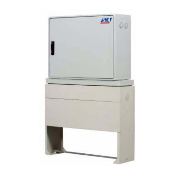
Technologie AG Description of the Sunny String Monitor Cabinet 2 Description of the Sunny String Monitor Cabinet The Sunny String Monitor Cabinet (SSM-C) enables connection of several strings in parallel. If failures occur in individual modules, or in the string cabling, they can only be detected with great effort, or not at all. - Page 9 Description of the Sunny String Monitor Cabinet Technologie AG Essential differences to the previous Sunny String Monitor: • Measurement in the negative and positive lines by means of variant configuration • Only suitable for grounded systems • Suitable for 1000 V DC •...
-
Page 10: General Safety Instructions
Any deviation from the instructions in this manual is regarded as inappropriate use of the equipment. SMA Technologie AG accepts no responsibility or liability for any and all damage resulting from inappropriate use of the equipment. -
Page 11: Checking The Delivery
On receipt of the equipment, check the packaging and the device for any possible damage and compare the contents of the delivery with the delivery documentation. In the case of damage to the device and/or unclear delivery contents, contact SMA Technologie AG immediately (contact address is in the appendix). -
Page 12: Special Hazards Of Grounded Pv Systems
Technologie AG General Safety Instructions Photovoltaic systems have special characteristics representing special hazards that are described here. An active power source is connected, which means that depending on the operating mode there may be voltage present, from the photovoltaic generator and/or the Sunny Central. -
Page 13: Cabling
General Safety Instructions Technologie AG 3.9 Cabling With regard to the SSM-C cabling, it must be ensured that the data lines and the DC main lines are laid separately. The distance between these two lines should be > 1 m. In the event of damage to the high voltage line, dangerous voltages can couple into the cable shield. -
Page 14: Disconnection
Technologie AG General Safety Instructions WARNING! If the isolation terminals are closed, the lower fuse holders are also energized when the string fuse is disconnected! The Plexiglas covers must always be mounted, to ensure protection against accidental touching! WARNING! Before inserting the string fuses, the correct polarity and ground fault protection must be ensured. - Page 15 General Safety Instructions Technologie AG Information We recommend the use of DC circuit breakers (optionally available) for isolating the inverter or the SSM-C. Even in the case of faults or fire, this allows system components to be isolated safely. Information Work on the SSM-C may be performed only after switching off the power to the unit.
-
Page 16: Operation
Technologie AG General Safety Instructions 3.12 Operation Apart from the optionally available DC circuit breaker, and the isolation terminals for PV plus and PV minus, there are no other control elements on the floor-mounted distribution board. Setting of parameters and querying of measurements occurs over the RS485 serial interface. -
Page 17: Parallel Connection Of Strings
Parallel Connection of Strings Technologie AG 4 Parallel Connection of Strings 4.1 Maximum Number of Strings per Measurement Input While the SSM-C is able to connect several strings in parallel, the analysis in the SCC is, however, limited to a maximum of nine, with a tolerance setting of 10 %. The maximum number of strings which can be connected in parallel in order to achieve reliable analysis in the SCC depends on the adjustable tolerance, and can be determined as follows:... - Page 18 Technologie AG Parallel Connection of Strings In the worst case, the voltage on the faulty string may lie within the MPP voltage (UMPP) of the remaining generator elements. The internal diode structure of the solar cells then causes reverse current to flow through the faulty generator string that, depending on the amount of current, may lead to excessive heating or destruction of the modules in this string! Among other symptoms, the following faults may lead to reduction of the open circuit...
-
Page 19: Structure Of The Ssm-C
Structure of the SSM-C Technologie AG 5 Structure of the SSM-C Depending on the chosen option, the SSM-C can be equipped with a load- disconnecting switch, and various numbers of string connections. The selection of SSM- C options or fittings can occur via the option code in the price list. This also defines the structure and identification of the SSM-C. - Page 20 Technologie AG Structure of the SSM-C Communication Piggy-Back Jumper for communication Data processing Piggy-Back LEDs for display of operating mode DC switch DC fuses Communication socket DC string connections: + pole DC main line: + pole Ground connection Overvoltage protectors DC string connections: - pole DC main line: - pole Depending on the selected fittings, the interior view of an SSM-C can differ from the...
-
Page 21: Installing The Floor-Mounted Distribution Board
Installing the Floor-mounted Distribution Board Technologie AG 6 Installing the Floor-mounted Distribution Board The SSM-C can be installed directly outdoors. Thus, the lengths of the DC string lines can be minimized reducing the losses on the DC side. NOTICE! Ensure that no moisture is enclosed within the housing when installing the SSM- C. - Page 22 Technologie AG Installing the Floor-mounted Distribution Board Information When installing the SSM-C, observe the installation guide which is provided in the base. The maximum burial depth for the base is 600 mm. To fill the base, one half (300 mm) must be filled with gravel or sand (grain size 2 - 4 mm), and the rest with so-called "base filler"...
- Page 23 Installing the Floor-mounted Distribution Board Technologie AG When burying, ensure that 1/4 of the second front panel remains visible. The first front panel should be freely accessible as it must be possible to remove this for any retrofitting work, or in the event of failure. 1 2 3 4 5 6 Page 20 SSM-TEN072310...
-
Page 24: Connection
Technologie AG Connection 7 Connection 7.1 Connection of the DC String Lines The connection of the string lines is realized by means of the isolation terminals on the mounting plate. To this end, the individual string lines must be routed into the housing's interior in a sealed manner. -
Page 25: Connection Of The Dc Main Lines
Connection Technologie AG 7.2 Connection of the DC Main Lines Connection of the DC main lines is realized by means of cable lugs at the provided bolt clamps. To this end, both DC main lines, like the string lines, must be routed into the housing's interior in a sealed manner. -
Page 26: Ground Connection
Technologie AG Connection 7.3 Ground Connection In order to guarantee the functioning of the integrated overvoltage protectors, it is mandatory to connect them to the external ground! To this end, a grounding cable (min. 16 mm²) is connected to the grounding terminal (see below) and grounded in the vicinity of the SSM-C (ground rod or similar). -
Page 27: Rs485 And Power Supply Connections
Connection Technologie AG 7.4 RS485 and Power Supply Connections 7.4.1 Cable Type for the Data Line Connection of the RS485 bus and the +55 V DC power supply in the SSM-C is to be realized by means of a single cable. The corresponding cable type must contain eight wires as twisted pairs, and have a minimum cross-section of 0.5 mm²... -
Page 28: Data Line Connection In The Ssm-C
Technologie AG Connection 7.4.3 Data Line Connection in the SSM-C WARNING! All SSM-Cs in the string must be disconnected via the load-disconnecting switches and the isolation terminals before connecting the data line. If there is no circuit breaker in the SSM-C, the DC fuses in the SC must be pulled in order to avoid reverse voltage from the inverter. -
Page 29: Ssm-C Termination
Sup +55V Un it / Hu FUSE RS48 RS48 Data Data Sunny Centr al +55V +55V .SMA Co ntr ENTE Not terminated SSM-C series Sunny Central Su nny Cen tra l Terminated Str ing Mo nit U1-A6 er Sup... - Page 30 Technologie AG Connection The jumper must be mounted on one SMU board so that the termination is activated. Jumper not Jumper mounted mounted 1 2 3 4 5 6 Termination is realized by means of: Mounting the jumper on an SMU board in the last SSM-C Removing the other jumpers on the SMU boards in the respective SSM-C Plugging the termination resistor into the RJ45 socket "485 Out"...
-
Page 31: Connection In The Sunny Central
+55V Unit Power / Hub FUSE RS485 RS485 Sun ny Data- Cen tral Data+ Sunny Central +55V +55V www. SMA.d trol ENTER Str ing Mo nit U1-A6 er Sup +55V Unit / Hub Power FUSE RS485 RS485 Data- Data+ Sunny... - Page 32 C e n U1-A6 +55V Power Sun ny String Monitor Cen tral Power Supply Unit / Hub RS485 Control ENTER FUSE RS485 Data- Data+ +55V +55V www.SMA.de 1 2 3 4 5 6 Technical Description SSM-TEN072310 Page 29...
- Page 33 Connection Technologie AG Noting the Serial Number After completion of installation work, and before connecting the DC voltage, you should make a note of the serial numbers of the data processing Piggy-Back (DVPB- SMU8HV). This is important for settings made later at the SCC, and for the grouping of the individual SMU boards in the SSM-C.
- Page 34 Technologie AG Connection After connection of the power supply for the SSM-C, it is possible to check that the cabling is correct in that the LEDs on the SMU board glow as described below. 1 2 3 4 1 2 3 4 5 6 LED 1 (green) Glows: overvoltage protector 1 ok Overvoltage protector...
-
Page 35: Configuration Of The Sunny Central
8.1 Sunny Data Control In general, the SSM-C can be configured using a PC and Sunny Data Control (SDC). SDC can be downloaded at www.SMA.de for free. Details on the use of SDC are available in the technical description of SDC. -
Page 36: Detection Of Ssm-Cs
Technologie AG Configuration of the Sunny Central 8.3 Detection of SSM-Cs "Device Set-up...SMUs...Devices" All SSM-C settings can be made here. SMU Devices Registration Detection Parameters Š Measured Values Before detection, make sure that no SSM-Cs have yet been detected, by means of the "Registration"... - Page 37 Configuration of the Sunny Central Technologie AG If SDC is being used, the system must be detected again within SDC after the SCC has detected the SMU boards. This is necessary for the devices to be visible in SDC's online display.
-
Page 38: Setting The Device Address
Technologie AG Configuration of the Sunny Central Checking the Detection The serial numbers found must match the actual serial numbers on the SMU8HV-DVPB (see figure below). 8.3.3 Setting the Device Address For identification of the individual SMU boards in the SSM-C, the device address "SSM Identifier"... - Page 39 Configuration of the Sunny Central Technologie AG The "SSM Identifier" setting is adjusted in the SSC's "Parameters" menu for the respective detected serial number. "Device Set-up...SMUs...Devices...Parameters" [ Parameters] SW version .....2.03 SSM Identifier ....2 "SSM Identifier" can also be set directly in SDC's SMU parameters. This allows the individual devices to be selectively allocated in sequence in the PV array.
-
Page 40: Deleting Detected Ssm-Cs
Technologie AG Configuration of the Sunny Central 8.4 Deleting Detected SSM-Cs It is also possible to delete SMU8HV-DVPB serial numbers which have already been registered for each SMU board. This is done by changing the ID number to 99. The ID number can be changed via the "Registration"... -
Page 41: String Current Monitoring Function
String Current Monitoring Function Technologie AG 9 String Current Monitoring Function The string currents are continually recorded by the respective data processing Piggy- Back (SMU8HV-DVPB) on the SMU board in the SSM-C, and averaged over a time period of 30 seconds. A mean value for each measuring channel is transferred to the SSC at 5 minute intervals. - Page 42 Technologie AG String Current Monitoring Function The dependence of the error sum on the tolerance setting and the triggering time is illustrated in the figure below. Totaling begins since the tolerance limit has been exceeded Actual string current = 6 A Tolerance limit at 10 % = 5.5 A The difference, which is totaled...
- Page 43 If you have questions relating to the correct parameter settings for the Sunny String Monitor, you can contact SMA directly on the Sunny Central Serviceline. The telephone number can be found in section 14 of this user manual. The adjustable parameters are described in the following sections.
-
Page 44: Setting String Current Monitoring Parameters
Technologie AG Setting String Current Monitoring Parameters 10 Setting String Current Monitoring Parameters 10.1 Triggering Time The triggering time is the time between the first occurrence of a failure at a measuring channel (deviation of string current outside the tolerance) and the display of a warning at the SCC, with an assumed constant tolerance. -
Page 45: Tolerance
Setting String Current Monitoring Parameters Technologie AG 10.2 Tolerance The individual string currents are detected per group and compared with the mean value of the group. The string current may only deviate from the group mean value by up to a maximum of the set tolerance (in % of the group mean value). If the tolerance is exceeded, then the excess value is totaled. -
Page 46: Configuring Groups
Technologie AG Setting String Current Monitoring Parameters The tolerance of the individual groups can also be set directly in the Sunny Data Control SCC parameters. 10.3 Configuring Groups The SCC is able to subdivide the individual measuring channels of the connected SMUs into three groups to make it possible to compare just measuring channels which have the same properties (orientation, radiation, shadowing). - Page 47 Setting String Current Monitoring Parameters Technologie AG The allocation of the individual measuring channels to the different groups is set directly, using the SMU parameters in the SCC: [ Parameters] Group Channel 8 ...1 Group all chan..2 Š "Device Set-up...SMUs...Devices...Parameters" Information Each individual measuring channel of an SMU can be allocated to a group in a freely selectable manner.
-
Page 48: Setting The Number Of Strings
Technologie AG Setting String Current Monitoring Parameters The allocation of the individual measuring channels to the different groups can also be set directly in SDC, using the SMU parameters. Group Classification with Team Configuration With the Team configuration, the SSM-C must be subdivided into at least two groups, and the SSM-Cs which are connected to the Team leader must be monitored in one group (e.g. - Page 49 Setting String Current Monitoring Parameters Technologie AG Under "Device Set-up...SMUs...Devices...Parameters", the number of connected strings per measuring channel used can be entered. [ Parameters] No.of Strings 1 ..2 No.of Str. All ..1 "Device Set-up...SMUs...Devices...Parameters" Information The number of strings per channel is freely selectable for the eight measuring channels.
-
Page 50: Time Windows
Technologie AG Setting String Current Monitoring Parameters The number of the individual strings per measuring channel can also be set directly in Sunny Data Control by means of the SMU parameters. 10.5 Time Windows In order to filter out temporary effects (e.g. shadowing in the morning, etc) on an individual string, it is possible to define a time window for every individual channel of the SSM-C. - Page 51 Setting String Current Monitoring Parameters Technologie AG Information Exactly one time window can be defined per measuring channel. "Device Set-up...SMUs...Devices...Parameters" The time of day when monitoring of the respective measuring channel is to start is entered here. The time of day when monitoring of the respective measuring channel is to stop is entered here.
- Page 52 Technologie AG Setting String Current Monitoring Parameters The time windows of the individual strings for each measuring channel can also be set directly in Sunny Data Control by means of the SMU parameters. Technical Description SSM-TEN072310 Page 49...
-
Page 53: Overnight Shutdown Setting
Setting String Current Monitoring Parameters Technologie AG 10.6 Overnight Shutdown Setting Due to the +55 V power supply, the SCC provides the option of overnight shutdown. In the default settings, overnight shutdown is activated in the SC ("ON"). Thus, the power supply to the SSM-Cs is deactivated in the SC as soon as the PV voltage has been <... -
Page 54: Setting The Anti-Theft Protection
Technologie AG Setting String Current Monitoring Parameters 10.7 Setting the Anti-Theft Protection The SSC provides the option of activating the anti-theft protection. To this end, alarm contact 2 on the SMU8HV must be incorporated into the monitoring circuit. The contacts at the solar modules are to be implemented as NC contacts, and connected to form a signal chain. - Page 55 Setting String Current Monitoring Parameters Technologie AG In combination with overnight shutdown, the anti-theft protection can be performed day and night. Upon interruption of the signal chain, an anti-theft warning appears in the SCC display, and an e-mail message is sent immediately. Under "Device Set-up SMUs Parameters", the anti-theft protection can be activated and deactivated.
-
Page 56: Values Of The String Current Monitoring System
Technologie AG Values of the String Current Monitoring System 11 Values of the String Current Monitoring System 11.1 Groups' Mean Values At the SCC, activate the submenu "SMUs" from the menu "Device Set-up". In the "Measured Values" submenu, the mean values of the measuring channels are displayed for each group, and updated at 5 minute intervals. -
Page 57: Measured Values Of The Measuring Channels
Values of the String Current Monitoring System Technologie AG 11.2 Measured Values of the Measuring Channels "Device Set-up...SMUs...Devices...Measured Values" Under this menu path, the currents of the individual measuring channels of the connected SMUs are displayed, and updated at 5 minute intervals. [Measured Values] I Channel 1 ..2.35A... -
Page 58: Warnings
Technologie AG Warnings 12 Warnings The warnings currently present, and the warnings history, can be displayed via the menu item "Failure". [ SMU Failures] actual Failures Hist. Failures "Device Set-up...SMUs...Failure" The individual meanings of the warnings and failures in the SCC can be found in the Sunny Central user manual. -
Page 59: Troubleshooting
Troubleshooting Technologie AG 13 Troubleshooting Danger to life For work to be carried out within the SSM-C, this device must be disconnected (see safety instructions in section 3.13). 13.1 Problems when Detecting the SSMs There are different reasons for problems arising when detecting the SMU boards in the SSM-C. - Page 60 Technologie AG Troubleshooting LED 1 (green) Glows: overvoltage protector 1 ok Overvoltage protector LED 2 (green) Glows: digital input / anti-theft protection ok Digital input (optional anti- theft protection) LED 3 (orange) Glows: data transfer active Data transfer LED 4 (red) Glows: fault on the string current monitoring system's Board fault control board...
-
Page 61: Contact
Contact Technologie AG 14 Contact Sunny Central on the Internet at: www.SMA.de You will find the following information at this site: • Latest information on the Sunny Central and the SSM-C • The latest version of the design tool for calculation of cable lengths •... - Page 62 The information contained in this document is the property of SMA Technologie AG. Publishing its content, either partially or in full, requires the written permision of SMA Technologie AG. Any internal company copying of the document for the purposes of evaluating the product or its correct implementation is allowed and does not require permission.
- Page 64 Sales Solar Technology www.SMA.de SMA Technologie AG Hannoversche Strasse 1–5 34266 Niestetal, Germany Tel. : +49 561 9522 4000 Fax: +49 561 9522 4040 E-Mail: Info@SMA.de Freecall: +800 SUNNYBOY Freecall: +800 7 8 6 6 9 2 6 9 Innovation in Systems Technology...
Need help?
Do you have a question about the Sunny String Monitor - Cabinet and is the answer not in the manual?
Questions and answers