Sign In
Upload
Download
Table of Contents
Contents
Add to my manuals
Delete from my manuals
Share
URL of this page:
HTML Link:
Bookmark this page
Add
Manual will be automatically added to "My Manuals"
Print this page
×
Bookmark added
×
Added to my manuals
Manuals
Brands
Perfect Prime Manuals
Data Loggers
TC0520 K
Instruction manual
Perfect Prime TC0520 K Instruction Manual
Datalogger thermometer
Hide thumbs
1
Table Of Contents
2
3
4
5
6
7
8
9
10
11
12
13
14
15
16
17
18
19
20
21
22
23
24
25
26
27
28
29
30
31
page
of
31
Go
/
31
Contents
Table of Contents
Bookmarks
Table of Contents
Table of Contents
1 General Description
2 Safety Information
3 Features
4 Speci Cations
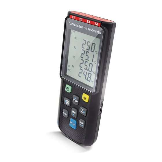
5 Symbol Definition and Button Location
Power ON/OFF Button
Backlight Button
Data-Hold Button
REC Button
MEM Button
RECALL Saved Reading Button
MAX/MIN/AVG Button
Selecting Temperature Units
SETUP Button
6 Button Instructions
7 Operating Instructions
Setup Options
Menu Item
Menu Description
Select Thermocouple Type
Setting Interval Time for Data Storing
Set O Set to Compensate for Probe Errors
Set Alarm Point (Only for Channel T1)
Set T1-T2 Subtraction Mode
Set Auto Power O Time
Set System Clock
Clearing Data Logger Records
Clearing Instant Read-Out Memory
Connecting to a Computer
8 Power Operation
Battery Replacement
9 Maintenance
10 Testlink SE-520 Software
Advertisement
Quick Links
1
General Description
2
Features
3
Rec Button
4
Setup Options
5
Setting Interval Time for Data Storing
6
Clearing Data Logger Records
7
Connecting to a Computer
8
Testlink Se-520 Software
Download this manual
Datalogger Thermometer
TC0520
Instruction Manual
Table of
Contents
Previous
Page
Next
Page
1
2
3
4
5
Advertisement
Table of Contents
Need help?
Do you have a question about the TC0520 K and is the answer not in the manual?
Ask a question
Questions and answers
Subscribe to Our Youtube Channel
Related Manuals for Perfect Prime TC0520 K
Thermometer Perfect Prime TC0521 Instruction Manual
Datalogger thermometer (43 pages)
Data Loggers Perfect Prime TC0301 Instruction Manual
Thermometer (16 pages)
Data Loggers Perfect Prime TC0376 Instruction Manual
Thermometer (27 pages)
Data Loggers Perfect Prime TC0309 Instruction Manual
Thermometer (16 pages)
Data Loggers Perfect Prime TC0520 J Instruction Manual
Datalogger thermometer (31 pages)
Data Loggers Perfect Prime TC0520 E Instruction Manual
Datalogger thermometer (31 pages)
Data Loggers Perfect Prime TC0520 T Instruction Manual
Datalogger thermometer (31 pages)
Data Loggers Perfect Prime TC0378 K Instruction Manual
Datalogger thermometer (31 pages)
Data Loggers Perfect Prime TH0165 Manual
Prime capsule portable data logger (8 pages)
Data Loggers Perfect Prime CO2000 User Manual
Co2/temp. /rh data logger (9 pages)
This manual is also suitable for:
Tc0520 j
Tc0520 e
Tc0520 t
Tc0521
Table of Contents
Save PDF
Print
Rename the bookmark
Delete bookmark?
Delete from my manuals?
Login
Sign In
OR
Sign in with Facebook
Sign in with Google
Upload manual
Upload from disk
Upload from URL


Need help?
Do you have a question about the TC0520 K and is the answer not in the manual?
Questions and answers