Table of Contents
Advertisement
OPERATING AND
INSTALLATION MANUAL
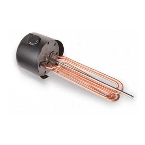
BUILT-IN ELECTRIC FLANGE HEATING UNIT
Družstevní závody Dražice - strojírna s.r.o.
Dražice 69, 294 71 Benátky nad Jizerou
Phone.: +420 /326 370 990
Fax: +420 / 326 370 980
E-mail:
export@dzd.cz
REU 18 - 2,5
RDU 18 - 2,5
RDU 18 - 3
RDU 18 - 3,8
RDU 18 - 5
RDU 18 - 6
RDW 18 - 7,5
RDW 18 - 10
RSW 18 - 12
RSW 18 - 15
SE 377
SE 378
Advertisement
Table of Contents

Related Manuals for Nibe Drazice REU 18-2,5


Summary of Contents for Nibe Drazice REU 18-2,5
- Page 1 OPERATING AND INSTALLATION MANUAL BUILT-IN ELECTRIC FLANGE HEATING UNIT REU 18 - 2,5 RDU 18 - 2,5 RDU 18 - 3 RDU 18 - 3,8 RDU 18 - 5 RDU 18 - 6 RDW 18 - 7,5 RDW 18 - 10 RSW 18 - 12 RSW 18 - 15 SE 377...
-
Page 2: Table Of Contents
CONTENTS PRODUCT TECHNICAL SPECIFICATION ....................... 4 ENERGY SAVING ............................4 OPERATION AND TEMPETATURE SETTING ....................4 OPERATION PRECONDITIONS ........................5 ASSEMBLY AND SAFETY INSTRUCTIONS ....................5 GENERAL INSTRUCTIONS ........................5 INSTALATION SCHEME ........................7 HEATING UNIT ASSEMBLY ......................... 8 ANTI-CORROSION PROTECTION INSTRUCTIONS ................9 ACCUMULATOR CONNECTION TO THE PRESSURIZED WATER MAIN .......... - Page 3 CAREFULLY READ THIS MANUAL BEFORE INSTALLING THE WATER HEATER! Dear Customers! The “R” heating element series by HPA Switzerland (Switzerland) and the “SE” series of heating elements by Winkelmann GmbH, Stahl-Behalter-Technik (Germany) are manufactured and tested accordingly with the valid ÖVE or VDE safety regulations. Their installation and putting into operation may only be implemented by assembly companies, following this manual.
-
Page 4: Product Technical Specification
1 PRODUCT TECHNICAL SPECIFICATION The R and SE series built-in electric flange heating units as main heaters for electric boilers are self-servicing. If calcium rich water is used, scale needs to be removed from the heating element in given time intervals. The user may set a temperature on the thermostat. -
Page 5: Operation Preconditions
4 OPERATION PRECONDITIONS The connection of a built-in electric flange unit must follow the data on the plate (operation pressure, heating time, el. voltage). Connecting to the electrics must follow the scheme on the inside of the protective cover. Aside from the electric regulations, the conditions of local distribution and water supply plants, as well as assembly and operation conditions, must be followed. - Page 6 Position of installation of elements of series: R, SE Correct Faulty Too long flange welded too high. Thermowell under the heating element. Vertical installation from the bottom Only R and SE types Correct Faulty The unit built in too high and in reversed position (the protective guard is up).
-
Page 7: Instalation Scheme
The flange rim must not exceed 130 mm, so that the temperature sensor and the element reach into the tank deep enough. Correct position of a built-in element assures even heating of the tank contents. In front of the flange, a +100 mm free space must be left for the assembly. Scale occurrence lowers functionality;... -
Page 8: Heating Unit Assembly
Adequate flanges: For all types For all types R…18…( ¤180 ) SE 377, SE 378 ( ¤255 ) 8 holes 10 holes 5.3 HEATING UNIT ASSEMBLY Aside from the installation regulations, the conditions of connection resulting from local distribution and water supply plants must be followed: 1. -
Page 9: Anti-Corrosion Protection Instructions
5.4 ANTI-CORROSION PROTECTION INSTRUCTIONS Heating unit maintenance involves checking and exchanging of the anode rod that is only contained in outputs from 2.5 to 6 kW. Magnesium anode sets the electric potential inside the tank to a level that limits boiler tank corrosion. Theoretically, its lifetime is calculated to two years of operation;... -
Page 10: Electrical Connection
5.6 ELECTRICAL CONNECTION Heating element assembly and its initial operation can only be implemented by an expert, who takes responsibility for proper implementation and equipment. The electrical connection must be implemented based on the attached scheme. The scheme related to a specific type is inside the plastic cover of the heating unit! The network voltage must be respected! All metal parts of the accumulator must meet relevant protective regulations. - Page 11 Connection scheme for SE 377, SE 378 The heating unit allows 3 types of connection. P = 3,2 kW Factory connection must not be changed! - 11 -...
- Page 12 Connection scheme for REU type 1/PE-N ∼ 230 V for RDU 2,5 kW – 5kW for RDU 6kW for RDW 7,5 kW, 10kW 3/PE ∼ 400 V 3/PE ∼ 400 V Star triangle - 12 -...
- Page 13 for RSW 18-12 & RSW 18-15 12/15 kW 3/PE ∼ 400 V triangle wiring of heating element external connection Connection is only possible with a contactor, not directly through the thermostat! - 13 -...
-
Page 14: First Putting Into Operation
5.7 FIRST PUTTING INTO OPERATION Before electric part connection, the accumulator must be filled with water. During the rating, water must drip off the safety valve. Warning: Both the hot water outlet pipe and safety armature parts may be hot. After heating, the set temperature of consumed water should roughly correspond with temperature shown on the thermometer. -
Page 15: Technical Data
8 TECHNICAL DATA Flange diameter 180 mm - REU 18, RDU 18, RDW 18, RSW 18 Flange diameter 255 mm - SE 377, SE 378 REU: Single-phase version for direct connection ∼ 230 V RDU, RDW, RSW, SE: Three-phase version for direct connection 3 ∼ 400 V Element lenght Type Output [kW]... -
Page 16: Disposal Of Packaging Material And Non-Functioning Product
9 DISPOSAL OF PACKAGING MATERIAL AND NON- FUNCTIONING PRODUCT A service fee for providing return and recovery of packaging material has been paid for the packaging in which the product was delivered. The service fee was paid pursuant to Act No 477/2001 Coll., as amended, at EKO-KOM a.s. The client number of the company is F06020274.
Need help?
Do you have a question about the Drazice REU 18-2,5 and is the answer not in the manual?
Questions and answers