Table of Contents
Advertisement
Quick Links
Advertisement
Table of Contents

Related Manuals for Gruetzner Lubricus LUB-D Series


Summary of Contents for Gruetzner Lubricus LUB-D Series
- Page 1 User manual LUB-D...
-
Page 2: Revision History & Imprint
All rights, including those of photomechanical reproduction, duplication and distribution by means of special processes (e.g. data processing, data carriers and data networks), even in part and/or in extracts, are reserved by Gruetzner GmbH. The content and technical specifications are subject to change without notice. -
Page 3: Table Of Contents
I.III Table of contents Chapter Content Page Revision history & imprint Revision history I.II Imprint of the manufacturer, distribution and service I.III Table of contents General information about this manual Signal words Warning symbols Structure of the safety instructions Symbols for information Safety EC/EU Directive Hazards... - Page 4 Chapter Content Page Mounting Preparations Assembly Commissioning Operation and settings General information Input and output signals - external control (PLC) Pin assignment Input signals 8.2.1 Control signal 2 seconds 8.2.1 Control signal 5 seconds 8.2.1 Control signal 8 seconds 8.2.2 Control signal 12 seconds 8.2.3 Control signal 14 seconds...
-
Page 5: General Information About This Manual
Any contradictory information contained in this user manual thus becomes invalid. If you have any questions regarding special applications, please contact Gruetzner GmbH (chapter I.II). The actual and factual operator must ensure and guarantee that these instructions, including any supplementary sheets, have been read and understood by all persons responsible for the installation, operation or maintenance of LUB-D. -
Page 6: Warning Symbols
Warning symbols The following warning symbols are used in this user manual to alert you to hazards, prohibitions and important information: General Electricity Flammable warning sign hazard material Structure of the safety instructions The safety instructions in this user manual are structured according to the following system: CAUTION This text explains the consequences of disregarding the... -
Page 7: Safety
Safety All persons working with LUB-D must follow these operating instructions, in particular the safety instructions and the rules and regulations applicable at the place of use. Generally applicable legal regulations and other rules as well as the relevant rules and regulations for accident prevention (e.g. -
Page 8: Usage For The Intended Purpose
LUB-D with defective protective devices; • operation of LUB-D without lubricant; • operation of LUB-D with non-approved lubricant; • operation of heavily contaminated LUB-D; • modifications or alterations which may be carried out without the written permission of Gruetzner GmbH have taken place; • opening and/or partial or complete disassembly of LUB-D. -
Page 9: General Safety Instructions
General safety instructions The following safety instructions are given for LUB-D: DANGER Damaged or flawed electrical connections or unlicensed hot components lead to heavy injuries or even death. • All work on electrical connections shall be provided by qualified personnel only. • Immediately change damaged cables or plugs. NOTICE Loose or overloaded screw connections can cause damage to LUB-D. -
Page 10: Description Of Function
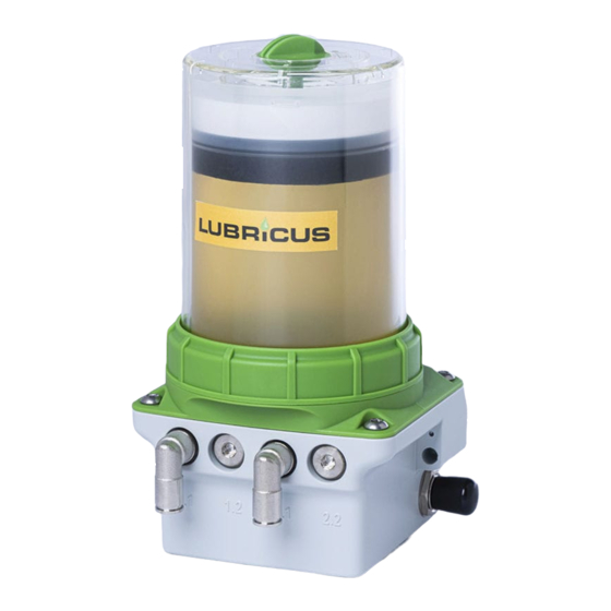
Description of function General information LUB-D is designed as an extremely compact double piston pump. The two pistons run force-controlled and counter-rotating. LUB-D is available with one, two, three or four lubricant outlets (see chapter 5). The outlets are secured by an integrated non-return valve. -
Page 11: Nameplate And Designation
Nameplate and designation The nameplate of LUB-D is visibly attached to the side of the pump itself. There the CE mark and the serial number of LUB-D are visible. Refer to chapter 3, Fig. 1 for the location of the nameplate and serial number. Scope of delivery LUB-D is available in several different versions. They differ in type (housing for 250 or 400 ml cartridge), number of outlets and accessories supplied. -
Page 12: Technical Data
Technical data Housing Dimensions without cartridge 107 x 56.5 x 108 Dimensions with housing 250 ml WxHxD 107 x 165 x 108 Dimensions with housing 400 ml 107 x 198.5 x 108 Weight (incl. empty cartridge, depending on 1285 - 1524 model) Mounting options holes for screw M6... -
Page 13: Transport And Storage
After receiving LUB-D check the delivery note for completeness and correctness. Any missing parts or damages must be reported immediately to the forwarding agent, the insurance company or Gruetzner GmbH in writing. Transport NOTICE Hard shocks due to e.g. falling or setting down too hard can damage LUB-D. -
Page 14: Versions
Versions LUB-D is designed as a compact central lubrication unit for supplying one or more lubri- cation points. Depending on the specifi c application LUB-D can also reliably and cleanly supply a limited number of lubrication points with lubricant. In this case accessories (e.g. splitters, progressive distributors or lubrication gears) can be connected to LUB-D in order to extend the number of lubrication points beyond the number of outlets. - Page 15 LUB-D-2 / LUB-D-2-250 Number of pump units (PU) Number of outlets Material Datum/Date Name VK-Artikel-Nr. Maßstab/Scale Warengruppe Maße in mm Gewicht/Weight DIN A4 J. Niederg. Bearb. 21.11.2017 1: 1 ,5 Gepr. J. Niederg. 21.11.2017 Differences in dosing volume per PU not applicable (only one PU) Dieses Dokument ist Eigentum von: This document is ownership of:...
-
Page 16: Lub
LUB-D-1-1 / LUB-D-1-1-250 Number of pump units (PU) Number of outlets Material Datum/Date Name VK-Artikel-Nr. Maßstab/Scale Warengruppe Maße in mm Gewicht/Weight DIN A4 J. Niederg. Bearb. 21.11.2017 1: 1 ,5 Gepr. J. Niederg. 21.11.2017 Differences in dosing volume per PU Dieses Dokument ist Eigentum von: This document is ownership of: Benennung / Title... -
Page 17: Lub
LUB-D-3 / LUB-D-3-250 Number of pump units (PU) Number of outlets Material Datum/Date Name VK-Artikel-Nr. Maßstab/Scale Warengruppe Maße in mm Gewicht/Weight DIN A4 J. Niederg. Bearb. 21.11.2017 1: 1 ,5 Gepr. J. Niederg. 21.11.2017 Differences in dosing volume per PU Dieses Dokument ist Eigentum von: This document is ownership of: Benennung / Title... -
Page 18: Lub
LUB-D-4 / LUB-D-4-250 Number of pump units (PU) Maßstab/Scale Material Gewicht/Weight Datum/Date Name Number of outlets VK-Artikel-Nr. Warengruppe Maße in mm DIN A4 21.11.2017 J. Niederg. Bearb. 1: 1 ,5 Gepr. 21.11.2017 J. Niederg. Differences in dosing volume per PU Dieses Dokument ist Eigentum von: This document is ownership of: Benennung / Title... -
Page 19: Mounting
Mounting Preparations Before starting to work, inform yourself in detail about LUB-D using this user manual; and follow the general safety instructions (section 2.7) in particular. Prepare the installation site carefully. NOTICE Pressurised air can damage the seals of LUB-D and can trans- port dirt and foreign matter into LUB-D or the lubricant. - Page 20 Remove cartridge cap Turn the cap of the lubricant cartridge counterclockwise and pull it off. Pay attention to cleanliness when carrying out the work. Be sure to prevent dirt, liquids and foreign bodies from entering the cartridge.
- Page 21 Mount lubricant cartridge Place the full lubricant cartridge on LUB-D (label facing front). Turn the lubricant cartridge clockwise onto LUB-D. The end position is reached after two full rotations when the label of the lubricant car- tridge is aligned with the front of LUB-D. Assemble housing on power unit Place the dismantled housing on LUB-D and press it onto the power unit.
- Page 22 Remove protective cap on the side of LUB-D Remove the black protective cap from the electrical interface on the side of LUB-D. Connect electrical interface To connect LUB-D with an external power supply system add a proper connecting cable to the electrical interface on the side of LUB-D.
-
Page 23: Commissioning
Commissioning Mount LUB-D carefully according to the steps described in chapter 5.2. Depending on the scope of delivery you must also carry out the following additional measures for first-time commissioning: 1. Mechanical fastening Fix LUB-D mechanically. Pay particular attention to the maximum tightening torques. 2. -
Page 24: Operation And Settings General Information
Operation and settings General information What you should know about operating and setting LUB-D: The disposable interchangeable cartridge with 250 or 400 ml lubricant guarantees a controlled and constant quality of the lubricant and is filled bubble-free. LUB-D allows a high supply security of the lubrication point and prevents failures. LUB-D cannot be used without a lubricant cartridge. Depending on the version ordered the cartridge can already be included in the scope of delivery and may already be connected and installed in LUB-D. -
Page 25: Input And Output Signals - External Control (Plc)
Input and output signals - external control (PLC) LUB-D operates as a pulse-controlled lubrication system only if unalterable input signals (high level) are transmitted from the PLC to LUB-D via PIN 2 in a defined sequence. LUB-D signals the respective status to the PLC via high/low levels which can be tapped off at PIN 4 and thus enables comprehensive control or, by suitable programming of the PLC, differentiated evaluation of the different states. To integrate LUB-D into an external control one input and one output must be provided on the control side. -
Page 26: Input Signals
Input signals LUB-D provides the following unalterably defined control signals (input signals) which must be transmitted from the PLC to LUB-D via PIN 2 of the electrical M12x1 interface as high level (+24 V DC). The control signals must be generated as high level (+24 V) by the external controller (PLC) over certain times with a tolerance of +/- 0.1 seconds. -
Page 27: Control Signal 2 Seconds
8.2.1 Control signal 2 seconds The control signal 2 seconds triggers a single dispensing process at pump body 1. After a specified pause time this control signal can be repeated or another control signal can be sent. The operating states are output by LUB-D via PIN 4 as a high/low level and must be tapped and processed accordingly by the PLC. - Page 28 Description: LUB-D is properly connected to an external controller via the electrical interface and connected to the power supply. LUB-D sends a permanent output signal (high level) to PIN 4 which indicates to the external control (PLC) that it is ready for operation. This output signal must be perma- nently and continuously present for >3 seconds to control LUB-D by a PLC.
-
Page 29: Control Signal 5 Seconds
8.2.2 Control signal 5 seconds The control signal 5 seconds triggers a single dispensing process at pump body 2. After a specified pause time this control signal can be repeated or another control signal can be sent. The operating states are output by LUB-D via PIN 4 as a high/low level and must be tapped and processed accordingly by the PLC. - Page 30 Description: LUB-D is properly connected to an external controller via the electrical interface and connected to the power supply. LUB-D sends a permanent output signal (high level) to PIN 4 which indicates to the external control (PLC) that it is ready for operation. This output signal must be perma- nently and continuously present for >3 seconds to control LUB-D by a PLC.
-
Page 31: Control Signal 8 Seconds
8.2.3 Control signal 8 seconds If your model provides two pump bodies, the control signal 8 seconds triggers a single dispensing process at each pump body one after the other. After a specified pause time this control signal can be repeated or another control signal can be sent. The operating states are output by LUB-D via PIN 4 as a high/low level and must be tapped and processed accordingly by the PLC. - Page 32 Description: LUB-D is properly connected to an external controller via the electrical interface and connected to the power supply. LUB-D sends a permanent output signal (high level) to PIN 4 which indicates to the external control (PLC) that it is ready for operation. This output signal must be perma- nently and continuously present for >3 seconds to control LUB-D by a PLC.
-
Page 33: Control Signal 12 Seconds
8.2.4 Control signal 12 seconds The control signal 12 seconds triggers the FIL function by the external control. A total of 40 dispensing operations are carried out automatically one after the other. After a certain pause time this control signal can be repeated or another control signal can be sent. The operating states are output by LUB-D via PIN 4 as high/low levels and must be tapped and processed accordingly by the PLC. - Page 34 Description: LUB-D is properly connected to an external controller via the electrical interface and connected to the power supply. LUB-D sends a permanent output signal (high level) to PIN 4 which indicates to the external control (PLC) that it is ready for operation. This output signal must be perma- nently and continuously present for >3 seconds. This condition must be fullfilled to control LUB-D by a PLC.
-
Page 35: Control Signal 14 Seconds
8.2.5 Control signal 14 seconds The control signal 14 seconds is used to acknowledge error messages. It is the only control signal that LUB-D can process when a low level output signal is sent. Regardless of the basic principle of remotly acknowledging an error it is essential to identify and eliminate the cause when an error message is present. - Page 36 Description: LUB-D is properly connected to an external controller via the electrical interface and connected to the power supply. There is an error at LUB-D. LUB-D sends a permanent output signal (high level) to PIN 4 which indicates to the external control (PLC) that it is ready for operation.
-
Page 37: Output Signals/Lcd Messages
Output signals Description Output signal (PIN 4) Chapter high, permanent ready for operation high, permanent received control signal low, 7...17 seconds dispensing process 0.5Hz square wave signal, permanent cartridge empty 8.3.1 low, permanent error If an output signal as low level (0V) is permanently present at PIN 4 for longer than 3s and no dispensing process is currently being performed by LUB-D, there is an error at LUB-D. -
Page 38: Empty Level (E1)
8.3.1 Empty level (E1) LUB-D is equipped with a sensor which detects the empty level of the lubricant cartridge. After reaching the empty level, LUB-D no longer dispenses lubricant. This ensures that no air enters LUB-D or the lubricant lines. The empty state message (E1) is transmitted to the external control (PLC). - Page 39 The transition of the output signals when changing a cartridge on LUB-D in switched-on state is shown and described below: PIN 4 E1 0,5 Hz E1 low Removing the empty cartridge Mounting the new cartridge Description: LUB-D is properly connected to an external controller via the electrical interface and connected to the power supply.
-
Page 40: Error: Overload (E2)
8.3.2 Error: overload (E2) Error "overload" (E2) signals a hydraulic overload during a dispensing process, e.g. if the maximum pressure is exceeded. PIN 4 >3s Description: LUB-D is properly connected to an external controller via the electrical interface and connected to the power supply. LUB-D has been successfully controlled by the external control (PLC) immediately before the occurrence of error E2 and has (attempted to) perform a dispensing operation. -
Page 41: Error: Undervoltage (E3)
8.3.3 Error: undervoltage (E3) Error "undervoltage/overvoltage" (E3) indicates that the power supply is not within the specified parameters. PIN 4 >3s Description: LUB-D is properly connected to an external controller via the electrical interface and connected to the power supply. If the supply voltage is too low, LUB-D sends a permanent output signal as low level (0 V) to PIN 4 for external control (PLC). -
Page 42: Fatal Error (E4)
8.3.4 Fatal error (E4) A "fatal error" (E4) indicates that the integrated microelectronics has detected a critical error and that LUB-D is not operating within the valid parameters. The cause can be mechanical, electronic or any other influencing variable. PIN 4 >3s Description: LUB-D is properly connected to an external controller via the electrical interface and connected to the power supply. -
Page 43: Maintenance And Disposal
Maintenance and disposal Before starting any maintenance work, inform yourself about the general safety instructions (see chapter 2) and observe the relevant local and operational safety regula- tions. Do not deactivate any protective device without authorization! Maintenance schedule The following maintenance schedule must be observed for LUB-D: Maintenace Commissio- After 500 hours... -
Page 44: Visual Check
9.1.1 Visual check Check the entire lubrication system (LUB-D and any connected accessories including tubes and distributors) for external damage (e.g. loose or loosened tubes) by a thorough and conscientious visual inspection. Check the condition of the lubrication point for correct supply of lubricant. Replace damaged or defective parts immediately to ensure permanent lubrication. -
Page 45: Cartridge Change
Cartridge change NOTICE A used lubricant cartridge must not be replaced on LUB-D as the integrated stroke counter of LUB-D is automatically reset by the cartridge sensor after a cartridge has been removed. • Only use full lubricant cartridges. NOTICE Only use original lubricant cartridges with lubricant approved by the manufacturer. - Page 46 Remove housing from power unit Separate the housing from the power unit by turning the retaining ring counterclockwise. Make sure that no dirt, water or foreign bodies enter the lubricant inlet. Remove empty cartridge Turn the empty cartridge clockwise to remove it.
- Page 47 Mount new lubricant cartridge Place the full lubricant cartridge onto LUB-D (label facing front). Turn the lubricant cartridge clockwise onto LUB-D. The end position is reached after two full rotations when the label of the lubricant car- tridge is aligned with the front label of LUB-D. Assemble housing on power unit Place the dismantled housing on LUB-D and press it onto the power unit.
-
Page 48: Disposal
Carry out the work as described above. If the empty state of the cartridge (error E1) was reached during a dispensing cycle, it is interrupted and continued automatically after completing the work explained above. Disposal When disposing LUB-D and empty or opened cartridges follow the relevant national regulations in force. -
Page 49: Released Accessories
Released accessories The present LUB-D can be considerably extended from use as a single point lubricator by the extensive system and accessory program. This may necessitate changes to the factory and/or the default settings of LUB-D to ensure reliable and proper operation of LUB-D combined with the hydraulically connected accessories. -
Page 50: Lubricants
10.1 Lubricants Only use lubricants approved by Gruetzner GmbH in the original cartridges developed and manufactured exclusively for LUB-D. NOTICE The lubricant used in each case differs according to the appli- cation. The respective designation can be found on the label of the cartridge. Further information on lubricants, documentation and safety data sheets can be obtained directly from Gruetzner GmbH. -
Page 51: Appendix
Appendix 11.1 Dimension sheet and installation dimensions LUB-D-250 min. 13,9 56,5 45,5 33,5 67,9 164,8... - Page 52 LUB-D 13,9 56,5 45,5 33,5 51,2 67,9 130,5 100,7 198,4...
-
Page 53: Ec/Eu Declaration Of Conformity
2004/108/EC. The following harmonized standards have been applied: EN 61000‐6‐2, EN 61000‐6‐4 electromagnetic compability Authorised representative for the compilation of technical documents: Volker Grützner, CEO, Gruetzner GmbH, Kohlenhofstr. 60, 90443 Nuremberg, Germany Nuremberg, 19.01.2021 Volker Grützner Gruetzner GmbH Kohlenhofstr. 60... -
Page 54: Flowchart Pulse Control Mode Pul
11.3 Flow chart impulse mode PUL The adjoining figure shows the basic flow Start chart for control signal 2 seconds (chapter 8.2.1) which triggers a stroke as well as possible errors. The flow chart shall help you creating a PIN 4 customized program for your external >3 seconds high? control (PLC). - Page 55 AUTOMATIC LUBRICATION AUTOMATIC LUBRICATION Gruetzner GmbH Kohlenhofstr. 60 • D - 90443 Nuremberg, Germany Tel. +49 911 277 399 0 • info@G-LUBE.com • www.G-LUBE.com...
Need help?
Do you have a question about the Lubricus LUB-D Series and is the answer not in the manual?
Questions and answers