Advertisement
FLS M9.50
BATCH CONTROLLER
SAFETY INSTRUCTIONS
General Statements
• Do not install and service the product without following the Instruction
Manual.
• This item is designed to be connected to other instruments which can be
hazardous if used improperly. Read and follow all associated instrument
manuals before using with it.
• Product installation and wiring connections should only be performed by
qualified staff.
• Do not modify product construction.
Installation and Commissioning Statements
• Remove power to the instrument before wiring input and output connections.
• Do not exceed maximum specifications using the instrument.
• To clean the unit, use only chemical compatible products.
PACKING LIST
Please verify that the product is complete and without any damage.
The following items must be included:
• M9.50 batch controller
• Instruction Manual for M9.50 batch controller
1
Advertisement
Table of Contents

Summary of Contents for FIP FLS M9.50 Series
- Page 1 FLS M9.50 BATCH CONTROLLER SAFETY INSTRUCTIONS General Statements • Do not install and service the product without following the Instruction Manual. • This item is designed to be connected to other instruments which can be hazardous if used improperly. Read and follow all associated instrument manuals before using with it.
-
Page 2: Technical Data
DESCRIPTION The new FLS M9.50 is a electronic device dedicated to control accurately batching or blending of different liquids. A 4” wide full graphic display shows measured values clearly and a lot of other useful information. Moreover, thanking to a multicolor display plus a powerful backlight, batching status can be determined easily from afar also. - Page 3 Electrical • Supply Voltage: 12 to 24 VDC ± 10% regulated • Maximum current consumption: 300 mA • FLS hall effect flow Sensor power: - 5 VDC @ < 20 mA - Optically isolated from current loop - Short circuit protected •...
-
Page 4: Panel Mounting
DIMENSIONS PANEL MOUNTING WALL MOUNTING INSTALLATION Mechanical installation The Batch Controller M9.50 is available just in one packaging for panel or wall installation. The panel version is installed using the panel mounting kit (M9.SN1), while the wall mounting version is got fixing the panel mounting version on the wall mounting kit (M9.KWX). - Page 5 Panel installation Fix instrument on the panel rotating by hand the fixing snails (M9.SN1). Wall installation Use the panel mounting kit (M9.SN1) to fix the M9.50 on the dedicated frontal cutout of the wall mounting kit (M9.KWX). Tighten front screws of box and waterproof connectors of cables, internally mount caps on screw sites to get a IP65 watertight installation.
-
Page 6: Power Wiring Diagram
• Remove the upper part of the terminals for an easy cabling. • Insert wire tip or ferrule completely into the terminal and fix with the screw until finger tight. • Do not route the sensor and DC power, cables in conduit containing AC power wiring. - Page 7 RELAY2 – BATCH RELAY WIRING DIAGRAM • Max voltage rating: 5A @ 240 RELAY 2 VAC resistive load. AC or DC • To reduce the possibility of Power noise interference, do not route signal cables together with AC power cable. Flow Flow REMOTE CONTROL WIRING DIAGRAM...
- Page 8 B. NO Signal Alarm OR Overrun Alarm Option • Max voltage rating: 5A @ 240 VAC AC or DC resistive load. RELAY 1 Power • To reduce the possibility of noise interference, do not route signal cables Alarm together with AC power cable. Device SOLID STATE RELAY 1 OR 2 –...
-
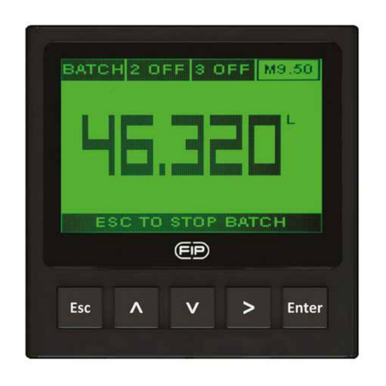
Page 9: Operational Overview
OPERATIONAL OVERVIEW The M9.50 batch controller features a full graphic display and a five-button keypad for system set-up, calibration and operation. Full graphic display has a white backlight during standard conditions, a red backlight in case a set alarm is activated (OVERRUN AND MISSING SIGNAL ALARM;... - Page 10 VIEW LEVEL MENU DIRECTORY (NOT RUNNING) Settings Volume batch Calibration Batch volume calibration Compensation value Outputs Totalizer Item Code - Software Release To select batch number Options Source solution volume in liters/percentage Click to enter the setting batch volume Resettable totalizers can be reset using on view level Click...
- Page 11 MENU LEVEL Click to choose batch Installation Data number which has to be fine-tuned Flow Unit password combination: Volume Unit Compensation in case of installation on Auto Calibration PVCC pipes, the K factor values Custom K factor are referred to T fittings type 1 SSR TFIFXXDC/BC 2 SSR...
-
Page 12: Output Mode
OUTPUT MODE The M9.50 Batch Controller features 2 solid state relays and 2 mechanical relays. 2 RELAY is dedicated only for managing of batch system. PROCEDURE FOR OUTPUTS SETTING - go to the “Options” menu - enter into the “Outputs activation” sub menu - enable output(s) - go to the “Outputs”... - Page 13 Digital outputs (1 RELAY, 1 SSR, 2 SSR) can be set in the following way: TWO STAGE SHUTDOWN (green backlight) - (icon reports TWO) Relay 90 % 100 % OUT 2 Option Relay OUT1 Batch Relay Batch Time OVERRUN ALARM (red backlight) - (icon reports OVR) Relay 100 % Status...
-
Page 14: Software Updating
SOFTWARE UPDATING In order to update the Instrument Software with a New Firmware Release follow the suggested procedures: TO UPDATE INSTALLED UNITS - Download the interface software “FLS Calibration System” and the Updated Software on www.flsnet.it - Launch the software "FLS Calibration System" on the laptop - Select OPTION and then UPGRADE FIRMWARE - Confirm the "Firmware Upgrade"... -
Page 15: Ordering Data
ORDERING DATA Description Power Wire power Sensor Part No. Output /Name supply Technology Input Panel Flow 2*(S.S.R.), M9.50.P1 mount Batch 12 - 24 VDC (Frequency) 2*(mech. relay) controller Wall mount Flow 2*(S.S.R.), M9.50.W1 Batch 12 - 24 VDC (Frequency) 2*(mech. relay) controller Wall mount Flow... - Page 16 FIP - Formatura Iniezione Polimeri S.p.A. Loc. Pian di Parata 16015 Casella Genova - Italy Tel. +39 010 96211 Fax +39 010 9621209 www.flsnet.it...
Need help?
Do you have a question about the FLS M9.50 Series and is the answer not in the manual?
Questions and answers