Table of Contents
Advertisement
Quick Links
Advertisement
Table of Contents

Subscribe to Our Youtube Channel
Related Manuals for Circutor CBS-400B


Summary of Contents for Circutor CBS-400B
- Page 1 Protection and monitoring relay CBS-400B INSTRUCTION MANUAL (M257B01-03-20A)
- Page 2 CBS-400B Instruction Manual...
-
Page 3: Safety Precautions
CIRCUTOR, SA reserves the right to make modifications to the device or the unit specifications set out in this instruction manual without prior notice. CIRCUTOR, SA on its web site, supplies its customers with the latest versions of the device specifica- tions and the most updated manuals. -
Page 4: Table Of Contents
CBS-400B CONTENTS SAFETY PRECAUTIONS ���������������������������������������������������������������������������������������������������������������������������������������������������������3 DISCLAIMER ��������������������������������������������������������������������������������������������������������������������������������������������������������������������������3 CONTENTS �����������������������������������������������������������������������������������������������������������������������������������������������������������������������������4 REVISION LOG �����������������������������������������������������������������������������������������������������������������������������������������������������������������������6 SYMBOLS �������������������������������������������������������������������������������������������������������������������������������������������������������������������������������6 1�- VERIFICATION UPON RECEPTION ������������������������������������������������������������������������������������������������������������������������������������ 7 2 - PRODUCT DESCRIPTION ������������������������������������������������������������������������������������������������������������������������������������������������� 7 3�- INSTALLATION OF THE DEVICE ���������������������������������������������������������������������������������������������������������������������������������������9 3�1�- PRELIMINARY RECOMMENDATIONS ������������������������������������������������������������������������������������������������������������������������9 3�2�- INSTALLATION ������������������������������������������������������������������������������������������������������������������������������������������������������� 10 3�3�- PANEL ADAPTER 72 x 72 mm ��������������������������������������������������������������������������������������������������������������������������������... - Page 5 CBS-400B 7�3�1�- VARIABLES OF THE CBS-400B AND INSTALLATION �������������������������������������������������������������������������������������� 38 7�3�2�- CHANNEL VARIABLES �������������������������������������������������������������������������������������������������������������������������������������39 7�3�3�- TRIPPING DUE TO TEST OR COMMUNICATIONS �������������������������������������������������������������������������������������������� 40 7�3�4�- EVENTS ������������������������������������������������������������������������������������������������������������������������������������������������������������ 41 7�3�5�- DEVICE CONFIGURATION VARIABLES �������������������������������������������������������������������������������������������������������������42 8�- TECHNICAL FEATURES ��������������������������������������������������������������������������������������������������������������������������������������������������45 8�1�- CBS-400B ��������������������������������������������������������������������������������������������������������������������������������������������������������������45 8�2�- WGB �����������������������������������������������������������������������������������������������������������������������������������������������������������������������47 9�- MAINTENANCE AND TECHNICAL SERVICE �������������������������������������������������������������������������������������������������������������������49...
-
Page 6: Revision Log
CBS-400B REVISION LOG Table 1: Revision log� Date Revision Description 01/20 M257B01-03-19A First Version Changes in the following sections: 09/20 M257B01-03-20A SYMBOLS Table 2: Symbols� Symbol Description In accordance with the relevant European directive. Device covered by European Directive 2012/19/EC. At the end of its useful life, do not discard of the device in a household refuse bin. -
Page 7: 1�- Verification Upon Reception
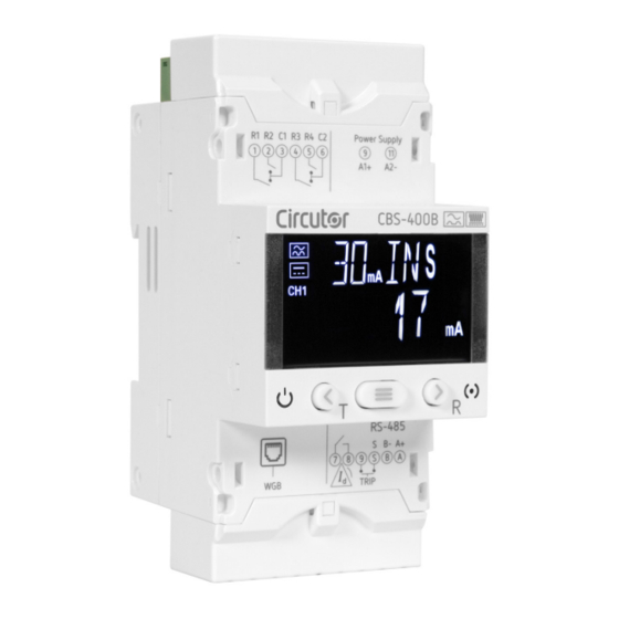
CIRCUTOR's after-sales service. 2 - PRODUCT DESCRIPTION The CBS-400B is a type B earth leakage protection and monitoring device (IEC 60755) with 4 inde- pendent channels, compatible with the earth leakage transformers in the WGB product range, and includes adjustable prealarm leakage sensitivity and integrated RS-485 communications. - Page 8 CBS-400B The transformers have: - 6 LEDs providing information about the transformer's status. - 2 RJ45 connection and power supply ports. Instruction Manual...
-
Page 9: 3�- Installation Of The Device
The CBS-400B device must be installed by authorised and qualified staff. The power supply plug must be disconnected and measurement systems switched off before handling, altering the connections or replacing the device. -
Page 10: 3�2�- Installation
Note: The 72 x 72 mm panel adapter is a separately sold accessory. CIRCUTOR has a panel adapter for CBS-400B devices so that it can be installed on 72 x 72 mm panels. illustrates how the panel adapter is connected to a CBS-400B. -
Page 11: 3�4�- Device Terminals
68 mm 68 mm Figure 2: Cut in the panel� 3�4�- DEVICE TERMINALS Figure 3: Terminals of the CBS-400B: Upper - Lower� Table 4: List of CBS-400B terminals� Device terminals 9: A1 +, Power supply 19: Prealarm, Digital output (NO) -
Page 12: 3�5�- Wgb Transformers
CBS-400B 3�5�- WGB TRANSFORMERS When the device is on, its terminals, opening covers or removing elements may ex- pose the user to parts that are hazardous to touch. Do not use the device until it is fully installed. The transformer is designed for wall-mounting or DIN-rail assembly with an accessory for installa- tion. -
Page 13: 3�5�2� Installation On A Din Rail
CBS-400B 3�5�2� INSTALLATION ON A DIN RAIL For installation on a DIN rail, a support bracket is provided with the device, see Figure 6 Figure 6: Support bracket� The steps to ensure proper installation are: 1�- Attach the bracket to the DIN rail. Be sure the side marked FRONT is visible. The bracket can be in-... -
Page 14: 3�5�3� Transformer Terminals
Figure 8: To remove the bracket use a screwdriver� 3�5�3� TRANSFORMER TERMINALS Figure 9: WGB terminals� Table 5: List of WGB terminals Device terminals 1, 2 Connection terminals to the CBS-400B and to the rest of WGB transformers. Instruction Manual... -
Page 15: 3�5�4� Transformer Leds
CBS-400B 3�5�4� TRANSFORMER LEDs WGB transformers have 6 indicating LEDs. Power Supply Channel TRIP Figure 10: WGB transformer LEDs� - Power (Blue color), indicates that the device is supplied power. - TRIP: (Red color), indicates that a leakage current trip has occurred. -
Page 16: 3�6�- Connection Diagrams
All active conductors that supply the loads or part of the installation where protection is required must pass through the associated WGB transformers For each of the channels to be monitored, connect the WGB transformer to the CBS-400B or to the next transformer in the installation, using the RJ45 cable,... - Page 17 Note: If a RJ45 connection cable other than the one supplied with the WGB is used, it must have a cross-section of 4 x 2 x AWG24/7. The maximum distance from the CBS-400B to the furthest WGB must be of 9 metres.
-
Page 18: 4�- Operation
CBS-400B 4.- OPERATION 4�1�- LED INDICATORS The CBS-400B device has 2 LEDs: - CPU, white color, indicates that the device is on. - ALARM, Table 7: ALARM LED� Description Red blinking: Indicates that a prealarm has been generated in one of the channels. -
Page 19: 4�2�- Display
Data area Unit and status areas Figure 15: CBS-400B display areas� The data area, which displays all the values measured by the device. The unit and device status area, which displays the different statuses, units and device in- formation (Table 8). -
Page 20: 4�3�- Keyboard Functions
CBS-400B 4�3�- KEYBOARD FUNCTIONS The CBS-400B has 3 keys to browse through the different screens and program the device. Function of the keys ( Table 9 Table 9: Function of the keys on display screens� Short keystroke Long keystroke (3s) -
Page 21: 5�- Display
If no key is pressed for 60 seconds, the device goes to the main display screen without updating the date and time. The display screen shows the icon , indicating that the CBS-400B clock has not been configured. shows the year setup screen. -
Page 22: 5�2�- Problems Or Changes In The Installation
CBS-400B Press key to increase the day value, and key to reduce it. Press key to confirm the value and skip to the hour configuration screen, Figure 20 Figure 20: Clock setup: Time� Press key to increase the hour value, and key to reduce it. -
Page 23: 5�3�- Display Screens
CBS-400B The device has detected WGB transformers that are not registered in the installation. The new installation has to be saved; this is carried out accessing the setup menu, see “6.6.1.- SAVE INSTALLATION”� 5�3�- DISPLAY SCREENS The display screens show the leakage current and the trip current and delay values of each channel,... -
Page 24: 5�4�- Trip Display Screens
CBS-400B Channel 4: Trip current (mA) Trip delay Total leakage current (alternating + direct) instantaneous (mA) Access the general setup menu by pressing the key for > 3s. (See "6.- CONFIGURATION" Note: If no key is pressed for 1 minute, the device goes to Channel 1's display screen. -
Page 25: 5�5�- Test Screen
CBS-400B When pressing key for > 3s, the relay returns to its initial status and is displayed for 3s Figure 23 before returning to the channel display screen. Figure 23: Reset� 5�5�- TEST SCREEN It is possible to carry out an individual test on each channel to verify the proper functioning of the relay. -
Page 26: 5�6 �- Direct Settings
CBS-400B 5�6 �- DIRECT SETTINGS From the channel's display screens, we can configure the trip current and delay for each of the relays. To do this, press key for > 3s while it displays the screen of the channel on which to apply the settings. -
Page 27: 5�6�3�- Delay And Relay Curve
To enter the event menu, we must display the Events screen and press the key for > 3s. The device displays the last 10 events generated in each channel. The CBS-400B saves 4 different types of events: TRIP, trip of a channel's relay. ALA, prealarm activated. - Page 28 CBS-400B Event 1 of channel 1: Event 1 of channel 1: Event 1 of channel 1: Prealarm Prealarm Prealarm Year Time Month and Day Event 5 of channel 2: Test Event 5 of channel 2: Test Event 5 of channel 2: Test...
-
Page 29: 5�8�- Other Screens
CBS-400B The register of events can be reset by communications, see "7.3.4 .- EVENTS". 5�8�- OTHER SCREENS While the CBS-400B is operating different screens can appear, indicating: Communication with the WGB of the channel being displayed has been lost. Instruction Manual... -
Page 30: 6�- Configuration
CBS-400B 6.- CONFIGURATION To enter the setup menu, we must display the Events screen and press the key for > 3s. The CBS-400B organises the device's configuration of the equipment into 6 menus, Figure 27 > 3 s. Access password >... -
Page 31: 6�1�- Rs-485 Communications
CBS-400B Figure 28: Password Screen� Use keys to modify the digit's value. Press key keys to skip the digit. To validate the value, hold down the key for > 3s; if the password is correct, in the bottom left of... -
Page 32: 6�1�2�- Peripheral Number
CBS-400B 6�1�2�- PERIPHERAL NUMBER This screen enables peripheral number configuration. Use keys to modify the value. Minimum value: 1. Maximum value: 247. To skip to the next programming point, press once the key Hold down the key for > 3s, to validate the data and exit the programming. -
Page 33: 6�2�- Prealarm
CBS-400B 6�2�- PREALARM shows the initial screen of the prealarm menu. Press the key for > 3s, to access the Figure 30 menu. Figure 30: Prealarm menu� In this menu we can configure the prealarm of each of the device's 4 channels. Icons indicate the channel that is being configured at any given time. -
Page 34: 6�3�- Channels
In this screen we can switch the channels detected by the CBS-400B, i.e. we can configure that chan- nel 1 detected by the CBS-400B becomes channel 2. Only one channel can be switched at a time, each time we enter the menu. -
Page 35: 6�4�- Clock Setup
CBS-400B 6�4�- CLOCK SETUP shows the initial screen of the setup menu. Press the key for > 3s, to access the menu. Figure 32 Figure 32: Clock setup menu� See section to set up the device's clock. "5.1.- CLOCK SETUP MENU"... -
Page 36: 6�6�- Installation
Figure 34 menu. Figure 34: Installation menu� 6�6�1�- SAVE INSTALLATION If the installation of the CBS-400B has been modified, i.e. the WGB transformers have been replaced (see ), the following screen appears to save the current configura- "3.7.- INSTALLATION CONNECTIONS"... -
Page 37: 7�- Rs-485 Communications
CBS-400B 7.- RS-485 COMMUNICATIONS The CBS-400B has an RS-485 communications port. The device is equipped with the MODBUS RTU communication protocol as standard. 7�1�- CONNECTIONS The RS-485 cable must be wired using twisted pair cable with mesh shield (minimum 3 wires), with a maximum distance of 1200 meters between the CBS-400B and the master unit. -
Page 38: 7�3�- Modbus Commands
All MODBUS map addresses are in Hexadecimal format. 7�3�1�- VARIABLES OF THE CBS-400B AND INSTALLATION Function 0x02 is used for these variables. Functions 0x01 and 0x05 are used for the variable Save the new installation. Table 10: Modbus Memory Map: CBS-400B-INSTALLATION (Table 1)� CBS-400B-INSTALLATION Parameter Format... -
Page 39: 7�3�2�- Channel Variables
CBS-400B Possible statuses of CBS-400B, Table 13 Table 13: Statuses of CBS-400B� Possible statuses CBS-400B Value Description Device in startup process Device idle Device tripped due to activation of the TRIP input 7�3�2�- CHANNEL VARIABLES Function 0x04: reading of registers, is used for these variables Table 14: Modbus Memory Map: Channel variables�... -
Page 40: 7�3�3�- Tripping Due To Test Or Communications
CBS-400B Possible statuses of WGB, Table 15 Table 15: WGB statuses� Possible statuses of WGB Value Description WGB in startup process WGB in idle status WGB tripped due to detected leakage current WGB tripped due to TEST with Test error result... -
Page 41: 7�3�4�- Events
CBS-400B Table 17 (Continued): Modbus Memory Map: Configuration of the trip and prealarm� Configuration of the Trip and Prealarm Configuration variable Format Address Valid data range Default value Tripping due to Communications bool 07D1 of channel 1 Tripping due to Communications... -
Page 42: 7�3�5�- Device Configuration Variables
CBS-400B 7�3�5�- DEVICE CONFIGURATION VARIABLES The following functions are used for these variables: Function 0x03: Reading of registers Function 0x10: Writing multiple registers. 7�3�5�1�- Configuration of the trip and prealarm Table 19: Modbus Memory Map: Configuration of the trip and prealarm�... - Page 43 CBS-400B Table 21: Modbus Memory Map: Trip current table� Trip current Address Parameter Format Function Value Channel 1 Channel 2 Channel 3 Channel 4 30 mA - 0 Value 1 Unit [16] 0x04 1014 10DC 11A4 126C 100 mA - 0...
- Page 44 CBS-400B 7�3�5�4�- Clock setup Table 24: Modbus Memory Map: Clock setup� Clock setup Configuration variable Format Address Valid data range Default value Clock setup Unit [32] 283C - 283D Date and time are given in Epoch format 7�3�5�5�- Password Table 25: Modbus Memory Map: Password�...
-
Page 45: 8�- Technical Features
CBS-400B 8.- TECHNICAL FEATURES 8�1�- CBS-400B AC Power supply Rated voltage 230 V ~ ± 15% Frequency 50 ... 60 Hz Consumption 11 VA Installation category CAT III 300V Monitoring features Rated frequency of the monitored circuit DC: 0 Hz - AC: 50 Hz - 1 kHz Rated residual non-operating current 0.5 Idn... - Page 46 Self-extinguishing V0 plastic Standards Low-voltage switchgear� Part 2: Automatic switch protection IEC 60947-2-M IEC 60755 General safety requirements for residual current operated protective devices Measurement conditions for Type B waveform specified in IEC 60755. 52.5 Figure 36: Dimensions CBS-400B� Instruction Manual...
-
Page 47: 8�2�- Wgb
CBS-400B 8�2�- WGB Electrical features Models WGB-35 WGB-55 WGB-80 WGB-110 Type Maximum rated current of the monitored circuit 80 A 160 A 250 A 400 A (In) Frequency 50... 1 kHz Maximum operating voltage ≤ 720 V ~, ≤ 750 V... - Page 48 WGB-xxx CBS-400B Ø6.5 Figure 37: WGB dimensions� Figure 38: WGB dimensions� WGB dimensions WGB-35 61.5 35,5 44.5 WGB-55 98.5 55.5 52.5 81.5 WGB-80 123.5 81.5 80.5 101.5 WGB-110 153.5 96.5 110.5 Instruction Manual...
-
Page 49: 9�- Maintenance And Technical Service
CBS-400B 9.- MAINTENANCE AND TECHNICAL SERVICE In the case of any query in relation to device operation or malfunction, please contact the CIRCUTOR, SA Technical Support Service. Technical Assistance Service Vial Sant Jordi, s/n, 08232 - Viladecavalls (Barcelona) Tel: 902 449 459 ( España) / +34 937 452 919 (outside of Spain) email: sat@circutor.com... -
Page 50: 11�- Ce Certificate
CBS-400B 11.- CE CERTIFICATE Instruction Manual... - Page 51 CBS-400B Instruction Manual...
- Page 52 CBS-400B Instruction Manual...
-
Page 53: Annex A.- Direct Settings
CBS-400B ANNEX A.- DIRECT SETTINGS > Password > > Trip current > < . . Delay and relay curve 0. N < > Instruction Manual... -
Page 54: Annex B.- Setup Menu
CBS-400B ANNEX B.- SETUP MENU > Password > . . Baud rate > > < . . > . . Peripheral > < > number < > N > Data format < N MEASURE... - Page 55 CBS-400B < > Channel 1 prealarm > > < current D Channel 1 prealarm operation MANU AUTO Channel 2 prealarm > < current D Channel 2 prealarm operation MANU AUTO > > Channel 3 prealarm >...
- Page 56 CBS-400B < > > Channel CHANNELS > < switching > < > > Year < > Month < > > > < > < > < > Hour > Password PASSWORD <...
- Page 57 CBS-400B Instruction Manual...
- Page 58 CIRCUTOR, SA Vial Sant Jordi, s/n 08232 - Viladecavalls (Barcelona) Tel: (+34) 93 745 29 00 - Fax: (+34) 93 745 29 14 www.circutor.es central@circutor.com...
Need help?
Do you have a question about the CBS-400B and is the answer not in the manual?
Questions and answers