Table of Contents
Advertisement
Quick Links
Advertisement
Table of Contents

Related Manuals for Circutor RGU-2


Summary of Contents for Circutor RGU-2
- Page 1 Earth leakage relay RGU-2 INSTRUCTION MANUAL (M98251301-03-16A)
- Page 2 RGU-2 Earth Leakage Relay Instruction Manual...
-
Page 3: Safety Precautions
CIRCUTOR, SA reserves the right to modify features or the product manual without prior notifi cation. DISCLAIMER CIRCUTOR, SA reserves the right to make modifi cations to the device or the unit specifi ca- tions set out in this instruction manual without prior notice. -
Page 4: Table Of Contents
RGU-2 Earth Leakage Relay CONTENTS SAFETY PRECAUTIONS ��������������������������������������������������������������������������������������������������������������������������������������� 3 DISCLAIMER ����������������������������������������������������������������������������������������������������������������������������������������������������������3 CONTENTS �������������������������������������������������������������������������������������������������������������������������������������������������������������4 REVISION LOG �������������������������������������������������������������������������������������������������������������������������������������������������������5 1�- VERIFICATION UPON RECEPTION ����������������������������������������������������������������������������������������������������������������� 6 2�- PRODUCT DESCRIPTION �������������������������������������������������������������������������������������������������������������������������������� 6 3�- UNIT INSTALLATION ���������������������������������������������������������������������������������������������������������������������������������������� 7 3�1�- PRIOR RECOMMENDATIONS������������������������������������������������������������������������������������������������������������������ 7 3�2�- INSTALLATION ������������������������������������������������������������������������������������������������������������������������������������������ 8 3�3�- UNIT TERMINALS �������������������������������������������������������������������������������������������������������������������������������������... -
Page 5: Revision Log
RGU-2 Earth Leakage Relay REVISION LOG Table 1: Revision log� Date Revision Description 10/13 M98251301-03-13A Initial Version 11/13 M98251301-03-13B Modified Figure 1 Modification section: 05/16 M98251301-01-16A 2.- 3.3. - 3.4. - 5.6.1. - 5.7.1. - 5.7.2. - 6 Instruction Manual... -
Page 6: 1�- Verification Upon Reception
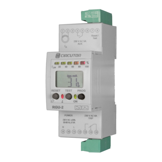
If any problem is noticed upon reception, immediately contact the transport company and/or CIRCUTOR's after-sales service. 2�- PRODUCT DESCRIPTION RGU-2 is a protection and/or measurement relay (MRCD/RCM). It is a smart earth leakage protection system composed of the following elements: - A detecting element or sensor,... -
Page 7: 3�- Unit Installation
The RGU-2 unit must be installed by authorised and qualified staff. The power supply plug must be disconnected and measuring systems switched off before han- dling, altering the connections or replacing the unit. -
Page 8: 3�2�- Installation
RGU-2 Earth Leakage Relay 3.2.- INSTALLATION The unit is installed on a DIN rail. All active conductors that supply the loads or the part of the installation where the earth leak- age protection with this unit is required must pass through the sensor associated with the unit. -
Page 9: 3�4�- Connection Diagram
RGU-2 Earth Leakage Relay 3.4.- CONNECTION DIAGRAM 3�4�1� AS A PROTECTION ELEMENT (MRCD) A�- SHUNT COIL TRIP (Manual reclosing system with RESET) Figure 2: Connection diagram of the unit as a protection element: shunt coil trip� B�- UNDERVOLTAGE COIL TRIP (Manual reclosing system with RESET) Figure 3:Connection diagram of the unit as a protection element: undervoltage coil trip�... -
Page 10: 3�4�2� As A Monitor (Rcm)
RGU-2 Earth Leakage Relay 3�4�2� AS A MONITOR (RCM) Figure 4:Connection diagram of the unit as a monitor� Instruction Manual... -
Page 11: 4�- Start-Up
RGU-2 Earth Leakage Relay 4�- START-UP 4.1.- DEFAULT CONFIGURATION When the unit is powered with auxiliary voltage, the ON LED is lit green and the LCD is backlit green. The name of the model, firmware version and a fixed screen that shows the conditions in which the earth leakage protection is characterised will be displayed. -
Page 12: 4�2�- Basic Setup
Adjust the trip delay time. Select the frequency of the installation to be supervised. 5�- OPERATION The RGU-2 unit helps control the electrical insulation level of an installation by controlling the intensity of the leakage current. Sensor block... -
Page 13: 5�2�- Display
RGU-2 Earth Leakage Relay TEST Key Press the TEST key to check the connection status of the sensor element and force the tripping of the unit. RESET key Locally rearms the electronic relay, resetting the status of the output contacts to the normal standby status. - Page 14 RGU-2 Earth Leakage Relay Instantaneous current screen ( Figure 10 Figure 10:Instantaneous current screen The trip current will be displayed when the protection element has been tripped ( Figure 11 Figure 11: Trip current screen (Example: 45mA trip current) Floating screens can also be displayed; they will be shown during 5 seconds and then return to the fixed active screen, such as: AUX relay prealarm screen (...
-
Page 15: 5�3�- Led Indicators
RGU-2 Earth Leakage Relay 5.3.- LED INDICATORS The unit has the following LEDs: LED ON Green LED, indicates that the unit is voltage-fed. The LED flashes when problems have been detected in the sensor. LEAKAGE LED Red LED indicates that the protection element has been tripped as a result of a residual current intensity value that is higher than the current threshold required to trip the protection element. -
Page 16: 5�5�- Outputs
RGU-2 Earth Leakage Relay 5.5.- OUTPUTS The unit has two independent output relays: 5�5�1� TRIP RELAY, TRIP Switched contact relay (terminals 13, 14 and 15 in Figure 1 The unit can be programmed to modify the logical status of the contact (refer to “5�6�3 FRE- QUENCY AND STATUS OF THE OUTPUT RELAY CONTACTS”) from the standard NC/NO... -
Page 17: 5�6�- Programming
RGU-2 Earth Leakage Relay 5.6.- PROGRAMMING 5�6�1 TRIP CURRENT I and TRIP DELAY TIME t Δn The earth leakage protection screen must be displayed to program the current and delay time of the trip. Hold down the PROG key for 2 seconds. -
Page 18: 5�6�2 Programming The Auxiliary Relay, Aux
RGU-2 Earth Leakage Relay table 4 (Continuation): Relationship of Currents and Trip Times to be programmed� Trip current IΔn Trip time td The trip curves are shown in Appendix A 5�6�2 PROGRAMMING THE AUXILIARY RELAY, AUX Open the auxiliary output screen and hold down the RESET key for 2 seconds to program the operation of the auxiliary relay. - Page 19 RGU-2 Earth Leakage Relay PROG Frequency (50Hz by default) PROG Select the frequency: 50Hz or 60Hz. Accept with the PROG key. RESET RESET RESET Status of the TRIP relay contact PROG (STD, by default) STD: Standard NC/NO status POS: NO/NC positive safety status...
-
Page 20: 5�6�4 Locking The Keyboard
RGU-2 Earth Leakage Relay 5�6�4 LOCKING THE KEYBOARD The unit has a series of devices that can be used to disable the programming operations (seal- able PROG button). However, the PROG key can be locked with the unit’s software by holding down the RESET and PROG keys for 2 seconds. -
Page 21: 5�7�- Trip Events
RGU-2 Earth Leakage Relay 5.7.- TRIP EVENTS When a circuit breaker has been activated, the LEDs, output contacts and display will indicate the cause that generated this situation. 5�7�1� EARTH LEAKAGE CURRENT INTENSITY TRIP LED ON LED, fixed. LEAKAGE LED, fixed. -
Page 22: 5�7�2� Local / External Test Trip
RGU-2 Earth Leakage Relay 5�7�2� LOCAL / EXTERNAL TEST TRIP LED ON LED, fixed. LEAKAGE LED, fixed. OUTPUT RELAYS The TRIP relay (terminals 13,14,15) changes its status. The AUX relay (terminals 4,5), only changes its status if it has been configured as a prealarm DISPLAY... -
Page 23: 5�8�- Reclosing System
2� The unit returns to the normal operating conditions after the RESET key has been pressed. 3� Finally, the ON circuit breaker is activated manually. Note: In case a contactor is used as a circuit breaker, reclosing the RGU-2 recloses the system with no need to perform any other operations. -
Page 24: 6�- Technical Features
RGU-2 Earth Leakage Relay 6�- TECHNICAL FEATURES Power Supply Voltage 120 ... 230V ~ Frequency 50 Hz - 60 Hz Maximun consumption 6 VA ( 230V ~) Voltage pulse Installation category CAT III 300V Current measurement circuit Sensor input Transformer type TP-WG, WG o WGC to 500/1... - Page 25 RGU-2 Earth Leakage Relay Figure 21:Dimensions of the RGU-2 Instruction Manual...
-
Page 26: 7�- Maintenance And Technical Service
• CIRCUTOR accepts no liability due to the possible damage to the unit or other parts of the installation, nor will it cover any possible sanctions derived from a pos- sible failure, improper installation or “improper usage”... -
Page 27: 9�- Ce Certificate
RGU-2 Earth Leakage Relay 9�- CE CERTIFICATE Instruction Manual... -
Page 28: Appendix A: Trip Curves
RGU-2 Earth Leakage Relay APPENDIX A: TRIP CURVES INSTANTANEOUS CURVE ( INS) Figure 22: Instantaneous Trip Curve� SELECTIVE CURVE ( SEL) Figure 23: Selective Trip Curve� Instruction Manual... - Page 29 RGU-2 Earth Leakage Relay Instruction Manual...
- Page 30 CIRCUTOR, SA Vial Sant Jordi, s/n 08232 -Viladecavalls (Barcelona) Tel.: (+34) 93 745 29 00 - Fax: (+34) 93 745 29 14 www.circutor.es central@circutor.es...
Need help?
Do you have a question about the RGU-2 and is the answer not in the manual?
Questions and answers