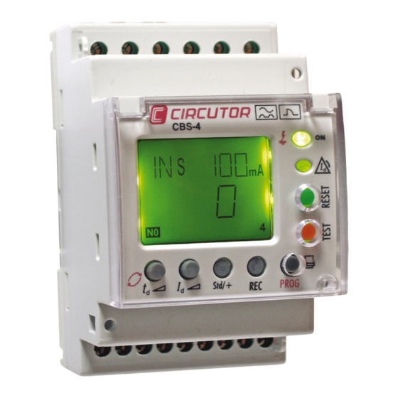
Circutor CBS-4 Series Instruction Manual
Multipoint earth leakage relay
Hide thumbs
Also See for CBS-4 Series:
- Instruction manual (29 pages) ,
- Manual (4 pages) ,
- Quick start manual (4 pages)
Table of Contents
Advertisement
Quick Links
Advertisement
Table of Contents

Related Manuals for Circutor CBS-4 Series


Summary of Contents for Circutor CBS-4 Series
- Page 1 Multipoint earth leakage relay CBS-4 series INSTRUCTION MANUAL (M98228301-03-18A)
- Page 2 CBS-4 series Instruction Manual...
-
Page 3: Safety Precautions
DISCLAIMER CIRCUTOR, SA reserves the right to make modifi cations to the device or the unit specifi ca- tions set out in this instruction manual without prior notice. CIRCUTOR, SA on its web site, supplies its customers with the latest versions of the device specifi cations and the most updated manuals. www.circutor.com CIRCUTOR, recommends using the original cables and accessories that are supplied with the device. -
Page 4: Table Of Contents
CBS-4 series CONTENTS SAFETY PRECAUTIONS ��������������������������������������������������������������������������������������������������������������������������������������� 3 DISCLAIMER ���������������������������������������������������������������������������������������������������������������������������������������������������������� 3 CONTENTS �������������������������������������������������������������������������������������������������������������������������������������������������������������4 REVISION LOG ������������������������������������������������������������������������������������������������������������������������������������������������������� 5 SYMBOLS ��������������������������������������������������������������������������������������������������������������������������������������������������������������� 5 1�- VERIFICATIONS UPON RECEPTION ������������������������������������������������������������������������������������������������������������� 6 2�- DESCRIPTION OF THE PRODUCT ������������������������������������������������������������������������������������������������������������������ 6 3�- INSTALLING THE DEVICE ������������������������������������������������������������������������������������������������������������������������������� 8 3�1�- PRELIMINARY RECOMMENDATIONS ���������������������������������������������������������������������������������������������������� 8 3�2�- INSTALLATION �����������������������������������������������������������������������������������������������������������������������������������������... -
Page 5: Revision Log
CBS-4 series REVISION LOG Table 1: Revision log� Date Revision Description 7/18 M98228301-03-18A New Version SYMBOLS Table 2: Symbols� Symbol Description In compliance with the relevant European directive. The device complies with the 2012/19/EC European directive. Do not dispose of the device in a household waste container at the end of its useful life. -
Page 6: 1�- Verifications Upon Reception
Perform an external visual inspection of the device before connecting it. d) Check that it has been supplied with the following: - An installation guide. Immediately contact the carrier and/or CIRCUTOR’s after-sales service if you detect any problem in the device upon reception. 2�- DESCRIPTION OF THE PRODUCT... - Page 7 - 2 Indicator LEDs. - 7 keys for the visualization and configuration of the device. - 4 relays to control the circuit breakers of the four channels - 1 Pre-alarm relay. - RS-485 communications, models CBS-4C and CBS-4C-NC. Table 3: Models CBS-4 series� RS-485 Model Status of the relays at rest communications...
-
Page 8: 3�- Installing The Device
CBS-4 series 3�- INSTALLING THE DEVICE 3.1.- PRELIMINARY RECOMMENDATIONS The operators using and handling the device must follow the safety measures established in the country where the device will be used to guarantee its safe operation, using personal protective equipment if needed. -
Page 9: 3�2�- Installation
CBS-4 series 3.2.- INSTALLATION The CBS-4 must be installed inside an electric panel or enclosure and mounted on a DIN rail (IEC 60715) or panel with an accessory (see “3.2.1.- INSTALLATION OF DEVICE IN PANEL .” While the device is connected, the terminals, opening the cover or removing el- ements can expose parts that are hazardous to the touch. -
Page 10: 3�3�- Terminals Of The Device
CBS-4 series Figure 2: Installation of adapter accessory 3.3.- TERMINALS OF THE DEVICE 3�3�1�- MODELS CBS-4 AND CBS-4C 14 15 Reset CBS-4 Test 4 5 6 Figure 3: CBS-4 and CBS-4C terminals� Table 4:Terminal description CBS-4 and CBS-4C� Terminal description... -
Page 11: 3�3�2�- Model Cbs-4C-Nc
CBS-4 series 3�3�2�- MODEL CBS-4C-NC 14 15 Reset CBS-4C-NC Test 4 5 6 Figure 4:CBS-4C-NC terminal� Table 5: Terminal description CBS-4C-NC� Terminal description Pre-alarma contact Output relay channel T4 (NC) A1, Auxiliary power supply 1S2, Common current input External trip - Reclose... -
Page 12: 3�4�- Connection Diagrams
CBS-4 series 3.4.- CONNECTION DIAGRAMS Note : It is recommended that meshed cable is used to connect the toroid over large distances. 3�4�1�- TRIP BY CURRENT EMISSION COIL In the event of an earth leakage relay trip due to a fault, test or error of the earth leakage current transformer. - Page 13 CBS-4 series Alimentación Auxiliar Power supply L1L2 L3 N L1L2 L3 N 14 15 Reset CBS-4C-NC Test L1L2 L3 N 4 5 6 L1L2 L3 N Figure 6: Trip by current emission coil (Model CBS-4C-NC) Instruction Manual...
-
Page 14: 3�4�2�- Trip By Current Undervoltage Coil
CBS-4 series 3�4�2�- TRIP BY CURRENT UNDERVOLTAGE COIL For connections via the current undervoltage coil, you need to activate the positive safety. (See “3.4.4.- CONNECTING THE DEVICE IN POSITIVE SAFETY” “5.1.3.-POSITIVE SECURITY SETTING OF THE RELAYS” In the event of an earth leakage relay trip due to a fault, test or error of the earth leakage current transformer. -
Page 15: 3�4�3�- Details Of The Current Transformer Connection
CBS-4 series 3�4�3�- DETAILS OF THE CURRENT TRANSFORMER CONNECTION Connection of differential transformers of the WGC / WGS series. Alimentación Auxiliar Power supply ON / OFF externo External ON/OFF 14 15 Reset CBS-4 Test 4 5 6 Figure 8: Details of the current transformer connection�... -
Page 16: 3�4�4�- Connecting The Device In Positive Safety
CBS-4 series 3�4�4�- CONNECTING THE DEVICE IN POSITIVE SAFETY This installation mode provides the most conservative protection from the point of view of per- sonal and property safety in electrical installations. With this type of device connection and setting, persons all goods are protected against faults where the earth leakage relay loses its protection capacity. -
Page 17: 4�- Operation
CBS-4 series 4�- OPERATION 4.1.- GENERAL DESCRIPTION DIN RAIL SMALL SIZE: PANEL ( ADAPTER ACCESSORY) 3 MODULE INSTANT CURRENT LEAKAGE BACKLIT DISPLAY LCD DISPLAY GREEN Normal operation status. RED Trip status by fault or other event. PRE-ALARM RELAY SENSITIVITY from 50 ... 80% I ∆N... -
Page 18: 4�2�- Description Of The Device
CBS-4 series 4.2.- DESCRIPTION OF THE DEVICE The front of the equipment which is formed by the display, buttons and LEDs, is protected with a sealable plastic cover which has the appropriate holes to access the RESET, TEST and PROG keys. -
Page 19: 4�4�- Keyboard Functions
CBS-4 series Table 7:LEDs description: Yellow LED� Yellow LED State Description There is no pre-alarm trip. Pre-alarm trip without reclosing. 4.4.- KEYBOARD FUNCTIONS The device has 7 keys, Figure 9 1�- Keys accessible with sealed cover and tool� RESET, Starts the equipment after a trip. -
Page 20: 4�5�- Display
CBS-4 series REC, This allows you to activate the automatic re-establishment option and use the device for signalling faults. Note: It must not be used as an earth leakage protection function. When activating the REC, the device automatically resets the trip relay, when the leak- age current drops below the programmed threshold once again. -
Page 21: 4�6�- Operation
CBS-4 series 4.6.- OPERATION When the device is powered at its rated voltage, the green LED ON the front is on, the backlit LCD is green indicating the software and hardware version. After a short while, the version disappears and the default display values appear on the display. -
Page 22: 4�7�- Troubleshooting Or Reasons For Tripping
CBS-4 series Table 15 (Continuation) : Parameters visible by display� Parameter Units + (contact 13-14 NC) / nothing (contact 13 - 14 NO) + (contact 15-14 NC) / nothing (contact 15 - 14 NO) Relay contact status + (contact 7- 8 NC) / nothing (contact 7 - 8 NO) -
Page 23: 4�7�3�- Fault Trip
CBS-4 series 4�7�3�- FAULT TRIP When the device is tripped by a current fault, the red and yellow LED comes on and the backlit LCD is red. There remains the display of the current of the last cycle that the relay has tripped. -
Page 24: 5�- Configuration
CBS-4 series 5�- CONFIGURATION 5.1.- DIRECT SETTING By pressing for a long time on any of the direct setting buttons, PROG mode is entered (icon on display) and change the relay. While in PROG mode if any other direct function is used (Id, td, Std/+ y Auto), the setting of the parameter in the relay viewed is also enabled. -
Page 25: 5�1�3�-Positive Security Setting Of The Relays
CBS-4 series 5�1�3�-POSITIVE SECURITY SETTING OF THE RELAYS “Std”, contacts are on standby, terminals 7 - 8 (NO), 9 - 8 (NO), 13 - 14 (NO) and 15 - 14 (NO). “+”, contacts change status on powering the device, the + sign is displayed. Terminals 7 - 8 (NC), 9 - 8 (NC), 13 - 14 (NC) and 15 - 14 (NC). -
Page 26: 5�2�- Setting By Setup
CBS-4 series 5.2.- SETTING BY SETUP “PROG” and the first menu option appear on the display by pressing a long time the PROG/ PAG key. Once in menu setting mode, the different text indicators appear on the display after each time PROG is pressed. When the correct menu is reached, the parameter can be changed by pressing td (rotating). -
Page 27: 5�3�- Configuration The Measurement Setup
CBS-4 series B�- CBS-4 configuration menu PROG PROG PROG PROG Figure 22: CBS-4C configuration menu. 5.3.- CONFIGURATION THE MEASUREMENT SETUP From measurement setup, the parameter settings for the CBS-4 can be displayed and/or changed; this may match these parameters to the requirements of the system topologies and/ or applications If it is an CBS-4C, this setup menu is preceded by the communications setup menu. -
Page 28: 5�3�2�- Scale Limit
CBS-4 series The possible adjustment values are: 50 Hz and 60 Hz� When the value on the screen is the required value, enter and move onto the next menu by pressing the PROG key. Setup is exited with the SAVE message. -
Page 29: 5�4�- Configuration The Communication Setup
CBS-4 series 5.4.- CONFIGURATION THE COMMUNICATION SETUP Note: Only for CBS-4C models. One or more CBS-4C devices may be connected to a computer or PLC in order to automate a production process or an energy control system. As well as the usual operation of each device, this system may centralize data at one single point;... -
Page 30: 5�4�2�- Baud Rate
CBS-4 series The peripheral number varies between 1 and 99. 5�4�2�- BAUD RATE The display shows the letters “bd” on the upper left of the screen showing the bauds and shows the baud rate in units of a thousand in the central part of the screen. - Page 31 CBS-4 series When the required value is on the screen, it is entered and the display moves on the next screen by pressing PROG, to allow the setting to be changed. For communication setting menu using setup ends on this screen. It directly links with the first measurement setup screen on the device. Instruction Manual...
-
Page 32: 6�- Rs-485 Communications
CBS-4 series 6�- RS-485 COMMUNICATIONS CBS-4C devices feature one RS-485 communications port. The device has uses the MODBUS RTU communications protocol as the standard protocol. 6.1.- CONNECTIONS The RS-485 cable must be wired with twisted pair cable with mesh shield (minimum 3 wires),... -
Page 33: 6�2�- Modbus Protocol
CBS-4 series 6.2.- MODBUS PROTOCOL In the Modbus protocol, the CBS-4C uses the RTU (Remote Terminal Unit) mode. The Modbus functions implemented in the device are as follows: Function 0x04: Reading integer registers. Function 0x10: Writing multiple registers. 6�2�1� READ EXAMPLE: Function 0x04�... -
Page 34: 6�3�- Modbus Commands
CBS-4 series No� of registers: 0005, No of registers to write: 5 No� of bytes: 0A, No of bytes that are sent: 10 Registers : 0001, Address 0000h: Peripheral number : 1 0003, Address 00001h: Baud rate : 3 = 19200 bds... - Page 35 CBS-4 series Table 12 (Continuation) : Modbus memory map Reading / Parameter Symbol Address Values Units Writing Effective value Current 001A leakage, Channel 1 Effective value Current 001B leakage, Channel 2 0 - 65.000 Effective value Current 001C leakage, Channel 3...
-
Page 36: 7�- Technical Features
Cut off power for CC loads Circutor guarantees that the CBS-4 device complies with a response time of less than 30 ms to 5In, and in combination with the selected cutting element must guarantee a total cut-off time of less than 40 ms to comply with the IEC 60947-2-M standard. - Page 37 CBS-4 series Earth leakage current measurement circuit Scale range Full scale Resolution Display 30 mA 75 mA ± 1 mA 300 mA 750 mA ± 1 mA 7.5 A ± 0.1 A 30 A 75 A ± 1 A Prealarm output...
- Page 38 CBS-4 series (Continuation) Standars UNE-EN 60947-2:2007 Low-voltage switchgear and controlgear - Part 2: Circuit-breakers Annexed M Standard for Ground-Fault Sensing and Relaying Equipment UL 1053 Depending on model. 52,5 Figure 24: CBS-4 dimensions� Instruction Manual...
-
Page 39: 8�- Technical Service
• CIRCUTOR accepts no liability due to the possible damage to the unit or other parts of the installation, nor will it cover any possible sanctions derived from a pos- sible failure, improper installation or “improper usage”... -
Page 40: 10�- Ce Certificate
CBS-4 series 10�- CE CERTIFICATE Instruction Manual... - Page 41 CBS-4 series Instruction Manual...
- Page 42 CBS-4 series Instruction Manual...
- Page 43 CBS-4 series Instruction Manual...
- Page 44 CIRCUTOR, SA Vial Sant Jordi, s/n 08232 - Viladecavalls (Barcelona) Tel: (+34) 93 745 29 00 - Fax: (+34) 93 745 29 14 www.circutor.es central@circutor.com...
Need help?
Do you have a question about the CBS-4 Series and is the answer not in the manual?
Questions and answers