Table of Contents
Advertisement
Quick Links
Advertisement
Table of Contents

Subscribe to Our Youtube Channel
Related Manuals for Circutor RGU-10A


Summary of Contents for Circutor RGU-10A
- Page 1 Protection and monitoring relay RGU-10A INSTRUCTION MANUAL (M359B01-03-22A)
- Page 2 RGU-10A Instruction Manual...
-
Page 3: Safety Precautions
CIRCUTOR S�A�U� reserves the right to make modifications to the device or the unit specifications set out in this instruction manual without prior notice. CIRCUTOR S�A�U� on its web site, supplies its customers with the latest versions of the device specifi- cations and the most updated manuals. -
Page 4: Table Of Contents
7�2�- TRIP RELAY ������������������������������������������������������������������������������������������������������������������������������������������������������������29 7�2�1 - POLARITY ���������������������������������������������������������������������������������������������������������������������������������������������������������30 7�2�2 - TRIP CURRENT LIMIT ���������������������������������������������������������������������������������������������������������������������������������������30 8- TECHNICAL FEATURES ��������������������������������������������������������������������������������������������������������������������������������������������������� 31 8�1 - RGU-10A ���������������������������������������������������������������������������������������������������������������������������������������������������������������� 31 8�2 - WGC ����������������������������������������������������������������������������������������������������������������������������������������������������������������������33 9 - MAINTENANCE AND TECHNICAL SERVICE �������������������������������������������������������������������������������������������������������������������37 10�- GUARANTEE ����������������������������������������������������������������������������������������������������������������������������������������������������������������37 11 - EU DECLARATION OF CONFORMITY ����������������������������������������������������������������������������������������������������������������������������38 ANNEX A - DIRECT SETTINGS ��������������������������������������������������������������������������������������������������������������������������������������������... -
Page 5: Revision Log
RGU-10A REVISION LOG Table 1: Revision log� Date Revision Description 11/22 M359B01-03-22A First Version SYMBOLS Table 2: Symbols� Symbol Description In accordance with the relevant European directive. Device covered by European Directive 2012/19/EC. At the end of its useful life, do not discard of the device in a household refuse bin. -
Page 6: 1�- Verification Upon Reception
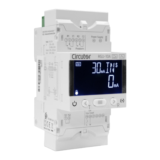
If any problem is noticed upon reception, immediately contact the transport com- pany and/or CIRCUTOR's after-sales service. 2 - PRODUCT DESCRIPTION The RGU-10A is a type-A ultraimmunised earth leakage protection and monitoring relay that is com- patible with the earth leakage transformers in the WGC range. The device features: - Display for showing the parameters. -
Page 7: 3�- Installation Of The Device
The RGU-10A device must be installed by authorised and qualified staff. The power supply plug must be disconnected and measurement systems switched off before handling, altering the connections or replacing the device. -
Page 8: 3�3 - Panel Mounting Accessory (72
3�3 - PANEL MOUNTING ACCESSORY (72 x 72 mm) Note: The 72 x 72 mm panel mounting accessory is sold separately. CIRCUTOR has a panel mounting accessory for the RGU-10A device so that it can be installed on 72 x 72 mm panels. -
Page 9: 3�4 - Device Terminals
Self-extinguishing V0 plastic 68 mm 68 mm Figure 3: Panel cut-out� 3�4 - DEVICE TERMINALS Figure 4: Terminals of the RGU-10A: Upper - Lower� Table 4: List of RGU-10A terminals� Device terminals A1: A1, Power supply 5: R2, Pre-alarm relay (NC) -
Page 10: 3�5 - Wgc Transformers
RGU-10A 3�5 - WGC TRANSFORMERS The transformer is designed for wall-mounting or DIN-rail assembly with an accessory for installation. The WGC is a feed-thru busbar type transformer, where the conductor cables to be measured must pass through the inner hole or window of the transformer. -
Page 11: 3�5�3 Distribution Of The Conductors In The Wgc
All the active conductors that feed the loads or part of the installation where earth leakage protection or monitoring is required must pass through the WGC transformer associated with the RGU-10A. Active conductors are defined as the phases (L1, L2 and L3) and neutral. Never the protection cable... - Page 12 RGU-10A Conductor routing must be neat, centred and separated from the transformer’s inner opening, Figure 11 Figure 11:Correct distribution of conductors� The inadequate arrangement of the conductors, as shown in , as well as not Figure 12 following the recommendations indicated in...
-
Page 13: 3�6 - Connection Diagrams
RGU-10A 3�6 - CONNECTION DIAGRAMS 3�6�1 CONNECTION WITH EMISSION COIL L1 L2 L3 N U > 2 3 4 5 Alimentación Auxiliar Power Supply CARGA LOAD 19 20 TRIP/RESET Figure 14: Connection diagram with emission coil� Instruction Manual... -
Page 14: 3�6�2 Connection With Undervoltage Coil
RGU-10A 3�6�2 CONNECTION WITH UNDERVOLTAGE COIL L1 L2 L3 N U < 2 3 4 5 Alimentación Auxiliar Power Supply CARGA LOAD 19 20 TRIP/RESET Figure 15: Connection diagram with undervoltage coil� Instruction Manual... -
Page 15: 4�- Operation
The measurement is a true RMS value, taken by using a residual current input from an external measurement toroidal transformer of the WGC series. The RGU-10A can be used to program and adjust all the parameters required to obtain complete pro- tection and control of the installation. -
Page 16: 4�3 - Display
RGU-10A Estado / State Figure 16: RGU-10A LED indicators� 4�3 - DISPLAY The device has a backlit LCD display that is split into two areas ( Figure 17 Data area Unit and status areas Figure 17: RGU-10A display areas� The data area, which displays all the values measured by the device, as well as the sensitivity or delay settings. -
Page 17: 4�4 - Keyboard Functions
An Individual test has been carried out, see “5.3 - TEST SCREEN”. An error has been detected, see "5.5 - ERROR SCREEN" 4�4 - KEYBOARD FUNCTIONS The RGU-10A has 3 keys to browse through the different screens and program the device. Function of the keys ( Table 7 Table 7: Function of the keys on display screens�... -
Page 18: 4�5 - Relay
RGU-10A 4�5 - RELAY The RGU-10A has 2 output relays, an R1 trip relay and an R2 pre-alarm relay ( Figure 18 to configure the parameters of the trip relay and "6 - DIRECT ADJUSTMENTS" "7.1 - PRE-ALARM RE- to configure the parameters of the pre-alarm relay. - Page 19 Trip relay R1 Entrada digital Digital input TRIP/RESET Figure 20: RGU-10A in idle� Relé de disparo R1 Trip relay R1 If the R1 trip relay is tripped, when a voltage is applied to the TRIP/RESET digital input, the RGU-10 RGU-10A disparado...
-
Page 20: Display
RGU-10A 5 - DISPLAY When starting the device, the home screen is displayed, showing the version of the device, Figure 22 and after 13 seconds the display screen is shown. Figure 22: Home Screen� Note: If the key is pressed, the device goes directly to the display screen. -
Page 21: 5�2 - Trip Display Screens
Screen with information on the device version. Press the key to see the version of the RGU-10A. 5�2 - TRIP DISPLAY SCREENS If a trip has been generated, the main display screen will be shown in red, the Alarm LED will be lit in red and the last cycle current that tripped the relay will be displayed. -
Page 22: 5�4 - Lock
RGU-10A Figure 24: Test screen� R for > 3s. The relay is returned to its idle status by pressing the key If the trip could not be carried out, the error screen ( ) is displayed for 3s before returning to Figure 25 the channel display screen. -
Page 23: 5�5 - Error Screen
RGU-10A Configuration values Table 8:Configuration values: Lock� Lock YES, the device is locked. Possible values NO, the lock on the device is deactivated. Hold down the key for > 3s, to validate the data and exit the programming. Note: If no key is pressed for 1 minute, the device will lock automatically. -
Page 24: 6�- Direct Adjustments
RGU-10A 6.- DIRECT ADJUSTMENTS The trip current and trip delay can be configured from the main display screen. To do this, press key Trip current > Delay and relay curve Figure 27: Direct settings� Note: If the device is locked, the direct settings cannot be modified and the screen shows the symbol . -
Page 25: 6�2 - Delay And Relay Curve
RGU-10A To skip to the next programming point, press once the key Hold down the key for > 3s, to validate the data and exit the programming. 6�2 - DELAY AND RELAY CURVE This screen is used to configure the delay of the relay trip or the type of trip curve. -
Page 26: 7�- Configuration
To enter the configuration menu, we must display the Events screen and press the key Note: If the device is locked, , the menu cannot be accessed. The device configuration on the RGU-10A is organised into 2 menus, Figure 28 Pre-alarm Relay >... -
Page 27: 7�1�1 - Pre-Alarm Current
RGU-10A Pre-alarm current > < > Delay of the > pre-alarm relay < > > Pre-alarm operation > < > Pre-alarm polarity > Figure 30: Pre-alarm relay configuration menu� 7�1�1 - PRE-ALARM CURRENT This screen is used to configure the current at which the pre-alarm will be activated according to the % of the relay's trip current. -
Page 28: 7�1�2 - Delay Of The Pre-Alarm Relay
RGU-10A 7�1�2 - DELAY OF THE PRE-ALARM RELAY This screen is used to configure the delay of the pre-alarm relay trip, in seconds. Press the key to enter edit mode, the programming value flashes. Use the keys to skip through the different options. -
Page 29: 7�1�4�- Polarity
RGU-10A 7�1�4�- POLARITY The polarity of the pre-alarm relay is configured in this section. Press the key to enter edit mode, the programming value flashes. Use the keys to skip through the different options. Configuration values Table 14:Configuration values: Polarity�... -
Page 30: 7�2�1 - Polarity
RGU-10A 7�2�1 - POLARITY The polarity of the trip relay is configured in this section. Press the key to enter edit mode, the programming value flashes. Use the keys to skip through the different options. Configuration values Table 15:Configuration values: Polarity�... -
Page 31: 8- Technical Features
RGU-10A 8- TECHNICAL FEATURES 8�1 - RGU-10A AC Power supply Rated voltage 230 V ~ ± 15% Frequency 50... 60 Hz Consumption 6.5 VA Installation category CAT III 300V Monitoring features Protection Type Type A ultaimmunised Sensitivity (IΔn) 0.03 - 0.1 - 0.2. - 0.3 - 0.5 - 0.75 - 1 - 1.5 - 2 - 3 - 5 - 10 - 30 A Adjustable trigger delay INS - [S] - 0.1 - 0.2 - 0.3 - 0.4 - 0.5 - 0.8 - 1 - 3 - 5 s... - Page 32 RGU-10A Mechanical features Terminals: A1, A2, 1 ... 8, 19, 20 2.5 mm ≤ 0.4 Nm, M2.5 Flat Cable from WGC to RGU-10A Maximum length 10 m Dimensions Figure 33 (mm) Weight 186 g Enclosure Self-extinguishing V0 plastic Standards Low-voltage switchgear and control gear� Part 2: Circuit-breakers� Annex M: Modular Re-...
-
Page 33: 8�2 - Wgc
RGU-10A 8�2 - WGC Measurement circuit Type Passant Network frequency 45... 60 Hz Assigned transformation ratio (Kn) 30 / 0.06 A Differential Current measurement circuit Scale range Scale found Display resolution 30 mA 75 mA ± 1 mA 300 mA 750 mA ±... - Page 34 RGU-10A (Continued) Mechanical features WGC 80 4 x 120 mm WGC 110 4 x 240 mm WGC 140 8 x 185 mm WGC 180 8 x 240 mm WGC 220x105 220 x 115 4 x 100 x 10 mm WGC 350x150...
- Page 35 RGU-10A Table 17: WGC 20 and WGC 30 Weight� Weight Model Weight WGC 20 60 g WGC 30 70 g Figure 36: WGC 25 and WGC 35 dimensions (in mm)� Ø Ø Figure 37: WGC 55, WGC 80, WGC 110, WGC 140 and WGC 180 dimensions (in mm)�...
- Page 36 RGU-10A Figure 38: WGC 220x105, WGC 350x150 and WGC 500x200 dimensions (in mm�)� Table 19: WGC 220x105, WGC 350x150 and WGC 500x200 dimensions� Dimensions (in mm) and Weight Model Weight WGC 220x105 54,2 3.740 kg WGC 350x150 50,2 7.800 kg WGC 500x200 11.300 kg...
-
Page 37: Maintenance And Technical Service
RGU-10A 9 - MAINTENANCE AND TECHNICAL SERVICE In the case of any query in relation to device operation or malfunction, please contact the CIRCUTOR S�A�U� Technical Support Service. Technical Assistance Service Vial Sant Jordi, s/n, 08232 - Viladecavalls (Barcelona) Tel: 902 449 459 (Spain) / +34 937 452 919 (outside of Spain) email: sat@circutor.com... -
Page 38: 11 - Eu Declaration Of Conformity
RGU-10A 11 - EU DECLARATION OF CONFORMITY Instruction Manual... - Page 39 RGU-10A Instruction Manual...
- Page 40 RGU-10A Instruction Manual...
-
Page 41: Annex A - Direct Settings
RGU-10A ANNEX A - DIRECT SETTINGS mA mA mA mA mA Trip current < > .A 30mA > A A .A .A .A .A 0. N Delay and relay curve < > (A1) Possible values if the trip current limit has been set ("7�2�2 - TRIP CURRENT LIMIT") to 30A�... -
Page 42: Annex B - Setup Menu
RGU-10A ANNEX B - SETUP MENU % Pre-alarm current > < > % < > Delay of the > < > pre-alarm relay < > > D < > > Pre-alarm operation MANU < > AUTO > < >... - Page 43 RGU-10A Instruction Manual...
- Page 44 CIRCUTOR S.A.U. Vial Sant Jordi, s/n 08232 - Viladecavalls (Barcelona) Tel: (+34) 93 745 29 00 - Fax: (+34) 93 745 29 14 www.circutor.com central@circutor.com...
Need help?
Do you have a question about the RGU-10A and is the answer not in the manual?
Questions and answers