Advertisement
ESP32-Ethernet-Kit V1.0 Getting Started Guide
This guide shows how to get started with the ESP32-Ethernet-Kit development board and also
provides informa on about its func onality and configura on op ons.
The
ESP32-Ethernet-Kit
devices to be interconnected over Wi-Fi. At the same me, to provide more flexible power
supply op ons, the ESP32-Ethernet-Kit also supports power over Ethernet (PoE).
What You Need
ESP32-Ethernet-Kit V1.0 board
USB 2.0 A to Micro B Cable
Computer running Windows, Linux, or macOS
You can skip the introduc on sec ons and go directly to Sec on
Overview
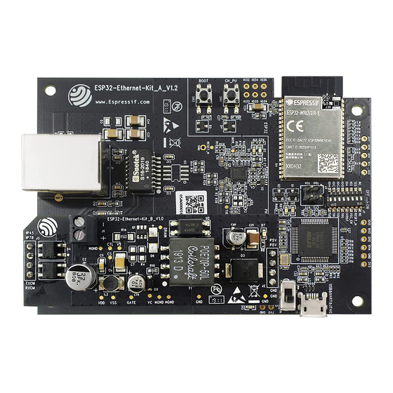
ESP32-Ethernet-Kit is an ESP32-based development board produced by Espressif.
It consists of two development boards, the Ethernet board A and the PoE board B, The
board (A)
contains Bluetooth / Wi-Fi dual-mode ESP32-WROVER-B module and IP101GRI, a
Single Port 10/100 Fast Ethernet Transceiver (PHY). The
Ethernet func onality. The A board can work independently, without the board B installed.
is an Ethernet-to-Wi-Fi development board that enables Ethernet
Start Applica on
PoE board (B)
provides power over
Development.
Ethernet
Advertisement
Table of Contents

Subscribe to Our Youtube Channel
Related Manuals for Espressif ESP32-Ethernet-Kit


Summary of Contents for Espressif ESP32-Ethernet-Kit
- Page 1 ESP32-Ethernet-Kit V1.0 Getting Started Guide This guide shows how to get started with the ESP32-Ethernet-Kit development board and also provides informa on about its func onality and configura on op ons. ESP32-Ethernet-Kit is an Ethernet-to-Wi-Fi development board that enables Ethernet devices to be interconnected over Wi-Fi.
-
Page 2: Functionality Overview
- an advanced mul -interface USB bridge. This chip enables to use JTAG for direct debugging of ESP32 through the USB interface without a separate JTAG debugger. Functionality Overview The block diagram below shows the main components of ESP32-Ethernet-Kit and their interconnec ons. -
Page 3: Functional Description
ESP32-Ethernet-Kit block diagram Functional Description The following two figures and tables describe the key components, interfaces, and controls of the ESP32-Ethernet-Kit. Ethernet Board (A) ESP32-Ethernet-Kit - Ethernet board (A) layout (click to enlarge) - Page 4 The table below provides descrip on star ng from the picture’s top right corner and going clockwise. Key Component Descrip on ESP32-WROVER-B This ESP32 module features 64-Mbit PSRAM for flexible extended storage and GPIO Header 2 Five unpopulated through-hole solder pads to provide access to selected GPIOs Flow Control A jumper header with access to the board signals.
-
Page 5: Setup Options
External Power Terminals Op onal power supply to the PoE board (B). Setup Options This sec on describes op ons to configure the ESP32-Ethernet-Kit hardware. Function Switch The func ons for specific GPIO pins can be selected with the Func on Switch. - Page 6 GPIO Allocation This sec on describes alloca on of ESP32 GPIOs to specific interfaces or func ons of the ESP32-Ethernet-Kit. IP101GRI (PHY) Interface The alloca on of the ESP32 (MAC) pins to IP101GRI (PHY) is shown in the table below.
- Page 7 Except for REF_CLK, the alloca on of all pins under the RMII Interface is fixed and cannot be changed either through IOMUX or GPIO Matrix. GPIO Header 1 This header exposes some GPIOs that are not used elsewhere on the ESP32-Ethernet-Kit. ESP32 Pin GPIO32...
- Page 8 ESP32 Pin RMII Func on Comments GPIO5 EMAC_RX_CLK See note 2 Note 1. The ESP32 pins GPIO16 and GPIO17 are not broken out to the ESP32-WROVER-B module and therefore not available for use. If you need to use these pins, please solder a module without SPIRAM memory inside, e.g.
- Page 9 ESP32-WROVER-B IP101GRI UART JTAG GPIO Comments IO26 RXD[1] IO27 CRS_DV IO14 IO14 IO12 IO12 IO13 IO13 IO15 IO15 See notes 1 and 3 below REF_CLK See notes 2 and 3 below nTRST IO16 IO16 (NC) See note 4 below IO17 IO17 (NC) See note 4 below Reset_N...
- Page 10 Start Application Development Before powering up your ESP32-Ethernet-Kit, please make sure that the board is in good condi on with no obvious signs of damage. Initial Setup 1. Set the Func on Switch on the Ethernet board (A) to its default posi on by turning all the switches to ON.
Need help?
Do you have a question about the ESP32-Ethernet-Kit and is the answer not in the manual?
Questions and answers