BIXOLON BCD-2000 User Manual
Customer display
Hide thumbs
Also See for BCD-2000:
- Manual (35 pages) ,
- Utility manual (17 pages) ,
- Installation manual & safety manual (4 pages)
Table of Contents
Advertisement
Quick Links
Advertisement
Table of Contents

Related Manuals for BIXOLON BCD-2000


Summary of Contents for BIXOLON BCD-2000
- Page 1 User’s Manual BCD-2000 Customer Display Rev. 1.02 http://www.bixolon.com...
- Page 2 BCD-2000 Introduction BCD-2000 is designed to be used while connected to computer peripherals and electronic devices such as ECR (Electronic Cash Register) and POS (Point Of Sales). ※ The main features of the printer are as follows: 1. Customer Display LCD Module Model 2.
-
Page 3: Table Of Contents
BCD-2000 Table of Contents 1. Product Models & Components ..................4 2. Unpacking ..........................5 2-1 BCD-2000A/AU/DS Types ....................5 2-2 BCD-2000N/NU Types ...................... 5 2-3 BCD-2000WA/WAU/WS Types ..................6 2-4 BCD-2000WN/WNU Types ....................6 3. Initial Settings & Options (Serial) ..................7 3-1 Direct Connection ...................... -
Page 4: Product Models & Components
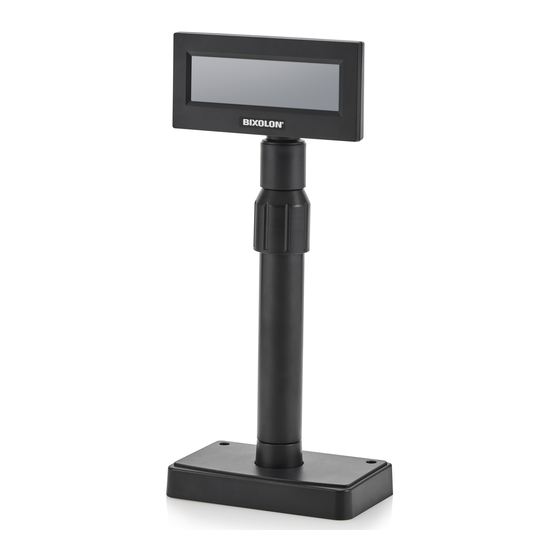
BCD-2000 1. Product Models & Components • The following display models are available: 1) Desktop (BCD-2000A/AU/DS) 2) Desktop Mount (BCD-2000N/NU) 3) Wall Mount (BCD-2000WA/WAU/WN/WNU/WS) BCD-2000A BCD-2000AU BCD-2000N BCD-2000NU BCD-2000DS BCD-2000WA BCD-2000WAU BCD-2000WN BCD-2000WNU BCD-2000WS * All models can be easily mounted on a wall or desk using an electric screwdriver. -
Page 5: Unpacking
BCD-2000 2. Unpacking 2-1 BCD-2000A/AU/DS Types Display Set Installation Guide Screws x 4 (M3x10) Tapping 2-2 BCD-2000N/NU Types Display Set Installation Guide Screws x 4 (M3x10) Tapping - 5 - Rev. 1.02... -
Page 6: Bcd-2000Wa/Wau/Ws Types
BCD-2000 2-3 BCD-2000WA/WAU/WS Types Display Set Installation Guide Screws x 4 (M3x10) Tapping 2-4 BCD-2000WN/WNU Types Display Set Installation Guide Screws x 4 (M3x10) Tapping - 6 - Rev. 1.02... -
Page 7: Initial Settings & Options (Serial)
BCD-2000 3. Initial Settings & Options (Serial) 3-1 Direct Connection • Connected to the Display directly without passing through the board. Item Display-Serial Standard Model BCD-2000N BCD-2000A Connect an SMPS to the Serial Cable Jack Voltage Used: 24V (2pin) How to... -
Page 8: Pass Through
BCD-2000 3-2 Pass Through • Data transmits through Host(PC) → Display → Printer. Item Display-Serial Standard Model BCD-2000DS Standard Board Specifications Power (Optional) 24V, 2.5A 24V, 1.5A Serial Cable 9PM to 25PF Cable Types (Optional) Power Cable 3P to 3P... -
Page 9: Connection Types & Sizes
BCD-2000 4. Connection Types & Sizes 4-1 Connection Types (BCD-2000A/N/DS/WA/WN/WDS) Standard Components (Host PC Side) (Printer Side) (Display Side) ▼ ▼ ▼ Interface Power 24VDC Connection 1 (Separate power supply needed Rinter/Display) Power 24VDC Connection 2 3 pin 3 pin (SMPS→Display... -
Page 10: How To Connect (Bcd-2000Au/Nu/Wau/Wnu)
BCD-2000 4-2 How to Connect (BCD-2000AU/NU/WAU/WNU) 1) Install the USB Virtual COM driver. 2) Connect the display cable to the USB port on a PC. 3) Turn on the PC and display. The PC will automatically detect new hardware connected to the USB port. -
Page 11: Sizes
BCD-2000 4-3 Sizes 4-3-1 Desktop Type 519mm 498mm 353mm 375mm 153mm 174mm 4-3-2 Wall Mount Type 173mm 152mm 4-3-3 Others 161mm 49mm 163mm 98mm 220mm 105mm Ø76mm BCD-2000A/AU BCD-2000DS - 11 - Rev. 1.02... -
Page 12: Features
BCD-2000 5. Features 5-1 Swivel • This device can be swiveled freely. Please follow the instructions below to avoid damage or malfunction when installing the device. To change the direction of the display after installation, follow the instructions provided below. -
Page 13: Tilting
BCD-2000 5-2 Tilting • The device can be tilted to the degree you want. Please follow the instructions below to avoid damage or malfunction when installing the device. It can be tilted up to 13° to each side with 4 levels and 5 positions. (Tilt: max. 52°) -
Page 14: Connection
BCD-2000 6. Connection 6-1 Connecting Direct Connection Pin 6-1-1 How to Install 1) Turn off the PC. 2) Connect the display cable to the RS-232 port on the PC. 3) Use a proper DC power adapter to connect the DC power. - Page 15 BCD-2000 6-1-2 Serial Cable Pin Layout (D-SUB 9PF) pin Name Short Connection 6-1-3 DC Power Jack MAX +24VDC. - Use only the genuine connection cable and adapter provided by the manufacturer. Caution or Warning - The warranty does not cover damage caused by the use of unauthorized cables.
-
Page 16: Serial Communication Connector (D-Sub 25Pf)
6-2-2 Host Interface Connector Pin Layout Input/ Signal Function Output Grounding of frame 1) BCD-2000 connected to pass through: Send data from printer to host Output 2) BCD-2000 connected independently: Send data from DM to host Receive data from host (Host → DM) -
Page 17: Usb Communication
BCD-2000 6-2-4 Printer Interface Connector Pin Layout Input/ Signal Function Output Input Receive data from printer (printer -> host) Output Send data to printer (DM -> printer) Indicate whether host is ready for incoming data Output transmission Grounding of signal... -
Page 18: Switch (Power, Brightness, Dip Switch)
BCD-2000 7. Switch (Power, Brightness, DIP Switch) 7-1 Power & Brightness Control Switches 7-1-1 Location • The Power and Brightness Control switches are located at the bottom of the display. Brightness Control Switch (knob) Power Switch Dark Bright 7-1-2 Function •... -
Page 19: Dip Switch
BCD-2000 7-2 DIP Switch 7-2-1 Location & Features • The 2 DIP switches are located on the backside of the panel. The DIP switch cover can be removed by pressing the hook. 7-2-2 Settings • RS-232 serial input and command emulation mode settings... -
Page 20: Vmsm (Virtual Memory Switch Manager)
Cursor display Cursor On 0, 1 5 ~ 7 Reserved Sleep mode selection Sleep mode off 0, 1 2) MSW 2 (BCD-2000 Setting) Memory Function Default Content to be set Range to be set 0: DTR/DSR Handshaking(BCD-2000) DTR/DSR 1: Xon/Xoff... - Page 21 BCD-2000 Vertical start BCD-2000: n = 0 position of the first BCD-2000K: n = 12 character BCD-3000: n = 0 BCD-2000: n = 0 character space BCD-2000K: n = 2 BCD-3000: n = 0 BCD-2000: n = 0 line space...
-
Page 22: Power Control
BCD-2000 8. Power Control • The base board is located inside the base unit. Remove the PCB cover by pressing the hook on the base unit as shown in the image below. Caution or Warning - Close the PCB cover before operation. - Page 23 BCD-2000 1) Jumper 1 Connection Mode Jack Type Input Power (24VDC) Position J1 Input Power (24VDC) Position CN1 Out power to print (24VDC) (Pass Through) Position CN2 2) Jumper 2 • Can be used when Data Pass Through mode or Printer Disabled mode is selected.
-
Page 24: Specifications
(cd/m²) Character [BCD-2000]: 30 x 4 (Letters) x (Lines) Number [BCD-2000K]: 20 x 2 [BCD-2000]: 95 Alphanumeric, 6 International Character Type(Set) [BCD-2000K]: 95 Alphanumeric, 30 International [BCD-2000]: 8*16 dot matrix Character Pattern (W) x (H) dot [BCD-2000K]:9*17 dot matrix [BCD-2000]: 4.24 x 8.48... - Page 25 BCD-2000 Warning - U.S.A This equipment has been tested and found to comply with the limits for a Class A digital device pursuant to Part 15 of the FCC Rules. These limits are designed to provide reasonable protection against harmful interference when the equipment is operated in a commercial environment.
- Page 26 BCD-2000 Revision history Rev. Date Page Description 1.00 10.05.17 1.01 12.28.17 20,21 Add New Emulation 1.02 26.07.18 Modified display area (AA, VA) - 26 - Rev. 1.02...
Need help?
Do you have a question about the BCD-2000 and is the answer not in the manual?
Questions and answers