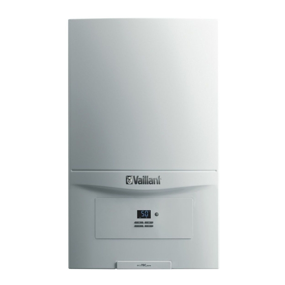
Vaillant ecoTEC sustain 24 Installation And Maintenance Instructions Manual

Vaillant ecoTEC sustain 24 Installation And Maintenance Instructions Manual

Table of Contents

Advertisement

ecoTEC sustain
24, 28, 34
en Installation and maintenance instructions

Advertisement

Table of Contents
loading

Summary of Contents for Vaillant ecoTEC sustain 24

  • Page 1 ecoTEC sustain 24, 28, 34 en Installation and maintenance instructions...
  • Page 2: Table Of Contents

    Installation and maintenance Start-up ............... 28 Carrying out the initial start-up......28 instructions Checking and treating the heating water/filling and supplementary water ........28 Contents Filling the condensate siphon ......29 Switching the product on and off ......29 Safety ..............4 Preventing low water pressure ......
  • Page 3 Recycling and disposal........43 Appendix ................44 Inspection and maintenance work ....44 Check programmes – Overview ....... 45 Overview of diagnostics codes ......45 Status codes – Overview ........49 Overview of fault codes ........50 Wiring diagrams..........52 Wiring diagram.............
  • Page 4: Safety

    Safety Qualification The person carrying out the work described Intended use here must have completed professional train- The product is intended as a heat generator ing. The competent person must demon- for sealed heating installations and for do- strably have all of the knowledge, skills and mestic hot water generation.
  • Page 5 ▶ Do not use any electrical switches, mains To prevent electric shocks, proceed as fol- plugs, doorbells, telephones or other com- lows before working on the product: munication systems in the building. ▶ Disconnect the product from the power ▶ Close the emergency control valve or the supply by switching off all power supplies main isolator.
  • Page 6: Regulations (Directives, Laws, Standards)

    List of relevant standards for Great Britain and Ireland ▶ Observe the national regulations, stand- ards, directives, ordinances and laws. You can find a list of relevant standards at: https://www.vaillant.co.uk/standards Installation and maintenance instructions ecoTEC sustain 0020253094_05...
  • Page 7: Guarantee And Customer Service

    To register your Vaillant appliance visit: https://self-service.vaillant.co.uk/warranty-registration Vaillant is a licensed member of the Benchmark Scheme. Benchmark places responsibilities on both manufacturers and installers. The purpose is to ensure that customers are provided with the correct equipment for their needs, that it is installed, commissioned and serviced in accordance with the manufacturer’s instructions by a competent person approved at the time by the Health and...
  • Page 8: Technical Data

    Technical data Technical data – General VUW 246/7-2 (H- VUW 286/7-2 (H- VUW 346/7-2 (H- Gas category II2H3P II2H3P II2H3P Diameter of the gas pipe 1/2" 1/2" 1/2" Diameter of the heating pipe 3/4" 3/4" 3/4" Diameter of the domestic hot water 3/4"...
  • Page 9 Technical data – G31 VUW 246/7-2 (H- VUW 286/7-2 (H- VUW 346/7-2 (H- Effective output range (P) at 50/30 °C 7.0 to 20.1 kW 8.0 to 20.1 kW 9.1 to 19.9 kW Effective output range (P) at 80/60 °C 6.4 to 18.5 kW 7.4 to 18.5 kW 8.4 to 18.5 kW Heat output range –...
  • Page 10 VUW 246/7-2 (H- VUW 286/7-2 (H- VUW 346/7-2 (H- Standby electrical power consump- 1.6 W 1.8 W 2.6 W tion Level of protection IPX4D IPX4D IPX4D Permissible connected voltage 190 to 253 V 190 to 253 V 190 to 253 V Installation and maintenance instructions ecoTEC sustain 0020253094_05...
  • Page 11: Notes On The Documentation

    Information on the Meaning identification plate Product article number Condensing techno- Efficiency class of the boiler in accord- ecoTEC sustain 24 VUW 246/7-2 (H- 0010019980 logy ance with EC Directive 92/42/EEC Serial number For quality control purposes; 3rd and 4th...
  • Page 12: Serial Number

    Reset any external controls, to resume normal operation of the central heating. If the boiler does not resume normal operation press the reset button. If the boiler does not resume normal operation after this call your Installation/Servicing company or Vaillant service. 5.6.2 Overheating Safety The boiler software is designed to recognise the potential for an overheat lockout and will shutdown before this happens.
  • Page 13: Set-Up

    Set-up Dimensions Checking the scope of delivery ▶ Check that the scope of delivery is complete and intact. 6.1.1 Scope of delivery Num- Designation Heat generator Bag with accessories: – Unit mounting bracket 58 58 – Bag with seals – Bag with bolts and wall plugs –...
  • Page 14: Installation Site

    Compartment Ventilation Unit mounting bracket Air/flue pipe connection R1 tundish/condensate The boilers are very high efficiency appliances. siphon connection As a consequence the heat loss from the appliance casing Consult the installation template that is supplied to find the during operation is very low. dimension A.
  • Page 15 6.6.2 Position of the air/flue terminal 6.6.2.1 Positioning the terminal of a fan-supported flue system Installation site Dimensions Adjacent to a boundary. 300 mm The dimension below eaves, balconies and car ports can be reduced to this value, as long as the flue terminal is 25 mm extended to clear any overhang.
  • Page 16 Installation site Dimensions The dimension below eaves, balconies and car ports can be reduced to this value, as long as the flue terminal is 25 mm extended to clear any overhang. External flue joints must be sealed with suitable silicon sealant. Above adjacent ground or balcony.
  • Page 17: Using The Installation Template

    6.6.3.3 Vertical Concentric Flue ⌀ 60/100 mm or 6.6.3 Flue Configuration Description ⌀ 80/125 mm (C33 type installation) 6.6.3.1 Horizontal Concentric Flue ⌀ 60/100 mm or ⌀ 80/125 mm (C13 type installation) Gasket (fitted) Consult the separate installation manual for air/flue gas sys- Note tems supplied with your appliance for all possibilities and as- If the terminal is at less than 1.80 m from the...
  • Page 18: Removing/Installing The Front Casing

    Removing/installing the front casing 6.10 Removing/installing the side section 6.9.1 Removing the front casing 6.10.1 Removing the side section ▶ Remove the front casing as shown in the illustration. Caution. 6.9.2 Installing the front casing Risk of material damage caused by mech- ▶...
  • Page 19: Installation

    Installation Descaling the water Scale deposition increases as the water temperature in- Preparing for installation creases. ▶ ▶ Make sure that the existing gas meter is capable of Descale the water as required. passing the rate of gas supply required. ▶...
  • Page 20 7.8.1.2 Direct connection to external soil and vent Note stack The condensate drain pipework must have a continuous fall (45 mm per metre) and should whenever possible terminate at a suitable drain point within the heated envelope of the building that will remain frost free under long periods of low external temperatures.
  • Page 21 7.8.1.5 External termination into soakaway 7.8.1.7 External termination into rain water down pipe Ø32mm ≤ 3 m < 500 mm 100 mm ≤ 3 m Ø22mm Ø 32mm Ø12 NB only combined foul/rainwater drain 7.8.1.8 Additional methods of introducing air breaks Ground (either/or) Bottom of sealed tube Seal...
  • Page 22: Installing The Discharge Pipe On The Expansion Relief Valve

    Installing the discharge pipe on the 7.10.2.1 Removing the connection piece for the expansion relief valve air/flue pipe Ensure that the pipeline is visible. Insert a screwdriver into the gap between the measur- Connect the expansion relief valve (1). ing points. The pipe must have a continuous fall and be routed Press the screwdriver carefully down.
  • Page 23 7.11.1 Opening the electronics box If required, shorten the connection cables. ≤ 30 mm ≤ 40 mm ≤ 30 mm Strip the flexible cables as shown in the figure. In doing so, ensure that the insulation on the individual conduct- ors is not damaged.
  • Page 24 7.11.5 Connecting controls to the electronics Observe the routing of the power supply cable (1) in the grommet in order to guarantee that there is no strain. Open the electronics box. (→ Page 23) 24 V – Burner 24V= X106 Limit thermostat for eBUS control or radio underfloor heating...
  • Page 25 7.11.6 Connecting additional components via VR 40 (2 in 7 multi-functional module) Install the components in accordance with the respect- ive instructions. Condition: Components connected to relay 1 ▶ Activate d.27. (→ Page 26) Condition: Components connected to relay 2 ▶...
  • Page 26: Operation

    ◁ Operation "no" appears in the display if the value cannot be set. Operating concept 11. Confirm by pressing 12. Press to cancel a setting or exit the installer level. The operating concept and the display and setting facilities of the operator level are described in the operating instruc- Using diagnostics codes tions.
  • Page 27 Press to return to the check programme. ◁ The display shows the check programme. Press to exit the check programme. ◁ OFF is shown in the display. ◁ The display changes to show the check pro- grammes. Press the button 2 times to exit the check programme.
  • Page 28: Start-Up

    Start-up Total Water hardness at specific system volume heating > 20 l/kW output ≤ 20 l/kW Carrying out the initial start-up > 50 l/kW ≤ 50 l/kW Initial start-up must be carried out by a customer service mol/ mol/ mol/ technician or an authorised competent person using the CaCO₃...
  • Page 29: Filling The Condensate Siphon

    Filling the condensate siphon Flushing the heating installation for the first time ("cold") Note The complete heating system must be flushed at least twice: Once with cold water and once with hot water in accordance with the following instructions. Check whether all thermostatic radiator valves and both service valves on the product are open.
  • Page 30: Filling The Hot Water Circuit

    2 minutes. ▶ Record the boiler maximum gas flow rate onto the Only Vaillant Service may perform a gas conversion. Benchmark gas boiler commissioning checklist. If a gas conversion to liquefied petroleum gas has been car- ried out, the smallest possible partial load is higher than is 9.9.3...
  • Page 31: Thoroughly Flushing The Heating Installation ("Hot")

    9.9.4 Checking the CO₂ content With the boiler operating at full load check that the gas inlet working pressure at the reference test point (2) Start up the product with the check programme and set complies with the requirements. the value. Permissible gas flow pressure for operation with –...
  • Page 32: Checking Leak-Tightness

    10.2 Burner anti-cycling time Note The actual reading on the digital pressure To prevent frequent switching on and off of the burner and gauge should ideally be 0,05 MPa (0,5 bar) thus prevent energy losses, an electronic restart lockout plus an additional pressure corresponding is activated for a specific period each time the burner is to the highest point of the system above the switched off.
  • Page 33: Setting The Maximum Heating Output

    10.3 Setting the maximum heating output Remaining feed head of the pump Pump curve The product's maximum heating output is set to automatic mode at the factory. If you want to set your own fixed max- Validity: VUW 246/7-2 (H-GB) imum heating output, however, you can specify a value un- OR VUW 286/7-2 (H-GB) der d.00 which equates to the product output in kW.
  • Page 34: Setting The Domestic Hot Water Temperature

    11 Handing over to the end user ▶ At the time of commissioning complete all relevant sec- tions of the Benchmark commissioning checklist, located at the rear of this document. ▶ For IE: Complete a “Declaration of Conformity” to indicate compliance to I.S.
  • Page 35: 12 Inspection And Maintenance

    12 Inspection and maintenance 12.5 Checking the CO₂ content Start up the product with the check programme (P.01) 12.1 Complete Service Interval Record section and set the value. ▶ – After servicing, complete the relevant Service Interval Setting value for the programme P.01: 100 Record section of the Benchmark Checklist located on Check programmes –...
  • Page 36: Setting The Co₂ Content

    12.6 Setting the CO₂ content Setting the CO₂ con- Removed Fitted front tent front casing casing Condition: The CO₂ content must be adjusted Liquefied pet- Liquefied pet- roleum gas P roleum gas P 10.1 ±0.2 vol. 10.3 ±0.2 vol. CO₂ at full load Set for Wobbe index 21.34 kW⋅h/m³...
  • Page 37: Cleaning The Heat Exchanger

    Do not undo the four nuts on the threaded pins (1), oth- erwise the tightness of the burner during set-up cannot Unscrew the retaining screw (1) and remove the air be guaranteed. intake pipe (2) from the intake stub. Clean the spiral immersion heater (3) of the heat ex- Unscrew the union nut from the gas valve assembly (3).
  • Page 38: 12.10 Cleaning The Condensate Siphon

    12.10 Cleaning the condensate siphon 12.12 Cleaning the heating filter Unclip the lower section of the siphon (1) from the up- per section of the siphon (2). Remove the float (3). Flush out the float and lower section of the siphon with water.
  • Page 39: 12.14 Draining The Product

    13 Troubleshooting Check that the sealing ring in the air intake pipe is posi- tioned correctly in the seal seat. Reconnect the air intake pipe to the intake stub. 13.1 Checking service messages Secure the air intake pipe with the retaining screw. appears, for example, if you have set a maintenance inter- 10.
  • Page 40: Deleting The Fault Memory

    13.4 Deleting the fault memory Remove the burner. Install a new seal (2) on the new burner. Clear the fault memory using diagnostics code d.94. Set a diagnostics code. (→ Page 26) 13.7.2 Replacing the fan or gas valve assembly 13.5 Resetting parameters to factory settings Reset all parameters to the factory settings using dia-...
  • Page 41 12. Refit the entire fan/gas valve assembly unit in reverse Note order. You must use a new seal (5) for this. Instead of grease, use only water or com- 13. Ensure that the order in which the three screws are mercially available soft soap to aid installa- screwed in between the fan and the mixture pipe cor- tion.
  • Page 42 13.7.5 Replacing the PCB 13.7.7 Replacing the expansion relief valve Remove the clip (2). Remove the expansion relief valve. Fit the new expansion relief valve with a new O-ring. Reattach the clip (2). 13.7.8 Replacing the volume flow sensor Prepare the repair work. (→ Page 40) Open the electronics box.
  • Page 43: Completing Repair Work

    ▶ Drain the product. (→ Page 39) 15 Recycling and disposal Disposing of the packaging ▶ Dispose of the packaging correctly. ▶ Observe all relevant regulations. ▶ For detailed information refer to www.vaillant.co.uk. 0020253094_05 ecoTEC sustain Installation and maintenance instructions...
  • Page 44: Appendix

    Appendix Inspection and maintenance work The table below lists the manufacturer requirements with respect to minimum inspection and maintenance intervals. If na- tional regulations and directives require shorter inspection and maintenance intervals, you should observe these instead of the intervals listed. Each time inspection and maintenance work is carried out, carry out the required preparatory and com- pletion work.
  • Page 45: B Check Programmes - Overview

    Maintenance work Interval Checking leak-tightness Annually Completing inspection and maintenance work Annually Check programmes – Overview Display Meaning P.00 Purging the domestic hot water and heating circuit: The function is activated in the small domestic hot water circuit for three minutes and then in the heating circuit for one minute.
  • Page 46 Dia- Values Factory set- gnostics Parameter Unit Increment, select, explanation Own setting ting Min. Max. code – – d.08 Status of the 230 V room Current value 0 = Room thermostat open (no thermostat (ON/OFF) heat requirement) adjustable 1 = Room thermostat closed (heat requirement) ℃...
  • Page 47 Dia- Values Factory set- gnostics Parameter Unit Increment, select, explanation Own setting ting Min. Max. code – d.27 Function of relay 1 1 = Circulation pump Adjustable (multi-functional module) 2 = External pump 3 = Cylinder charging pump 4 = Extraction hood 5 = External solenoid valve 6 = External fault message 7 = Solar pump (omitted)
  • Page 48 Dia- Values Factory set- gnostics Parameter Unit Increment, select, explanation Own setting ting Min. Max. code – – – d.66 Activation of the warm off = Function deactivated Adjustable start function for do- on = Function activated mestic hot water –...
  • Page 49: D Status Codes - Overview

    Status codes – Overview Note Since the code table is used for various products, some codes may not be visible for the product in question. Status code Meaning Displays in heating mode S.00 Heating mode: No requirement S.01 Heating mode: Fan prerun S.02 Heating mode: Pump prerun S.03...
  • Page 50: E Overview Of Fault Codes

    Overview of fault codes Note Since the code table is used for various products, some codes may not be visible for the product in question. If faults occur, some of them can be reset. To do so, press and hold the button for three seconds.
  • Page 51 Fault code Meaning Possible cause Flow/return NTC temperature difference too great → flow and/or return tem- F.72 Fault: Deviation in the water pressure sensor/return temperature sensor perature sensor defective F.73 Fault: Water pressure sensor not con- Interruption/short circuit of water pressure sensor, interruption/short to earth nected or has short-circuited in supply pipe to water pressure sensor or water pressure sensor defective F.74...
  • Page 52: F Wiring Diagrams

    Wiring diagrams Wiring diagram Validity: VUW 246/7-2 (H-GB), VUW 286/7-2 (H-GB) Burner off RT 24V X106 eBUS – Burner 24V= 230V~ 230Vac Main PCB Gas valve assembly Interface PCB Prioritising diverter valve Safety thermostat for underfloor heating Pressure sensor 24 V DC room thermostat Volume flow sensor Bus connection (digital room thermostat/control) External ignition device...
  • Page 53: Wiring Diagram

    Wiring diagram Validity: VUW 346/7-2 (H-GB) Burner off RT 24V X106 eBUS – Burner 24V= 230V~ RT 230Vac 230Vac Main PCB Gas valve Interface PCB Diverter valve Safety thermostat for underfloor heating Pressure sensor 24 V DC room thermostat Mass flow- Bus connection (digital room thermostat/controller) External ignition device Outside temperature sensor, wired...
  • Page 54: Commissioning Checklist

    Commissioning Checklist Benchmark Commissioning & Warranty Validation Service Record It is a requirement that the boiler is installed and commissioned to the manufacturers’ instructions and the data fields on the commissioning checklist completed in full. To instigate the boiler warranty the boiler needs to be registered with the manufacturer within one month of the installation.
  • Page 55 GAS BOILER SYSTEM COMMISSIONING CHECKLIST & WARRANTY VALIDATION RECORD Address: Boiler make and model: Boiler serial number: Commissioned by (PRINT NAME): Gas Safe registration number: Company name: Telephone number: Company email: Company address: Commissioning date: Heating and hot water system complies with the appropriate Building Regulations? Time, temperature control and boiler interlock provided for central heating and hot water Boiler Plus requirements (tick the appropriate box(s)) Weather compensation...
  • Page 56 SERVICE & INTERIM BOILER WORK RECORD It is recommended that your boiler and heating system are regularly serviced and maintained, in line with manufacturers’ instructions, and that the appropriate service / interim work record is completed. Service provider When completing a service record (as below), please ensure you have carried out the service as described in the manufacturers’ instructions. Always use the SERVICE/INTERIM WORK ON BOILER SERVICE/INTERIM WORK ON BOILER Date:...
  • Page 57 SERVICE & INTERIM BOILER WORK RECORD It is recommended that your boiler and heating system are regularly serviced and maintained, in line with manufacturers’ instructions, and that the appropriate service / interim work record is completed. Service provider When completing a service record (as below), please ensure you have carried out the service as described in the manufacturers’ instructions. Always use the SERVICE/INTERIM WORK ON BOILER SERVICE/INTERIM WORK ON BOILER Date:...
  • Page 58: H Commissioning Flow Chart

    Commissioning Flow Chart PRIOR TO CO AND COMBUSTION RATIO CHECK NOTE The boiler manufacturer’s installation instructions should have been followed, gas type verified and gas THE AIR GAS RATIO VALVE IS FACTORY supply pressure/rate checked as required prior to commissioning. SET AND MUST NOT BE ADJUSTED As part of the installation process, especially where a flue has been fitted by persons other than the DURING COMMISSIONING UNLESS THIS...
  • Page 59: Index

    Index Guarantee and Customer Service......... 7 Handing over to the end user ..........34 80/125 mm diameter unit connection piece, installing ..22 Heat exchanger, cleaning............ 37 Heat exchanger, replacing ..........41 Air/flue pipe connection on the unit ........22 Heating installation, filling............
  • Page 60 Unit connection piece, removing ......... 22 Validity of the instructions............ 11 Volume flow sensor ............. 42 Weight ................. 17 Installation and maintenance instructions ecoTEC sustain 0020253094_05...
  • Page 64 Supplier Vaillant Ltd. Nottingham Road Belper Derbyshire DE56 1JT Telephone 0330 100 3461 info@vaillant.co.uk www.vaillant.co.uk 0020253094_05 Publisher/manufacturer Vaillant GmbH Berghauser Str. 40 D-42859 Remscheid Tel. +492191 18 0 Fax +492191 18 2810 info@vaillant.de www.vaillant.de © These instructions, or parts thereof, are protected by copyright and may be reproduced or distributed only with the manufacturer's written consent.

Table of Contents