
Related Manuals for Vaillant ecoTEC plus 412


Summary of Contents for Vaillant ecoTEC plus 412
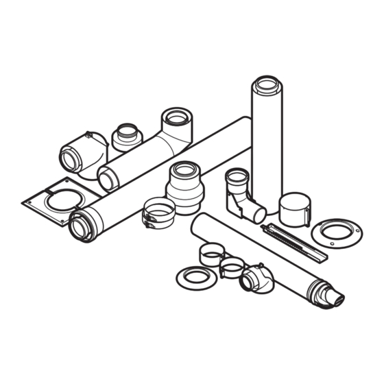
- Page 1 ecoFIT sustain, ecoFIT pure, ecoTEC sustain, ecoTEC pro, ecoTEC plus, ecoTEC exclusive VU../VUW../VUI.. en Air/flue pipe installation manual...
-
Page 2: Table Of Contents
Air/flue pipe installation manual 5.17 Installing the flue gas pipe on the external wall............... 43 Contents 5.18 Installing the concentric connection, 60/100 mm diameter, to the air/flue system for negative pressure ..........48 Safety ..............3 5.19 Installing the sliding sleeve, elbows and Action-related warnings ......... -
Page 3: Safety
Safety General safety information 1.3.1 Risk caused by inadequate Action-related warnings qualifications Classification of action-related warnings The following work must only be carried out The action-related warnings are classified in by competent persons who are sufficiently accordance with the severity of the possible qualified to do so: danger using the following warning symbols –... - Page 4 ▶ Ensure that this ice formation does not lubricant is supplied with the product, use this lubricant. slide from the roof. Mortar residues, shavings, etc., in the flue 1.3.7 Risk of damage to the structure of the gas route may prevent the flue gas from flow- building due to moisture ing outdoors as intended, and this flue gas As a result of improper installation, water may...
-
Page 5: Ukca/Ce Certification
Vaillant article num- bers that are designed for the air/flue pipe is provided. If you do not use certified Vaillant air/flue pipe elements when installing the heat generators, this voids the UKCA/CE conformity of the heat generator. -
Page 6: Notes On The Documentation
Notes on the documentation Observing other applicable documents ▶ You must always observe the installation instructions for the installed heat generator. Storing documents ▶ Pass these instructions and all other applicable docu- ments on to the end user. Validity of the instructions These instructions apply only for the heat generators named in the other applicable documents, hereinafter referred to as the "product". -
Page 7: Certified Air/Flue Systems And Components
Certified air/flue systems and components System overview, 60/100 mm diameter – products until 2024 Article number Air/flue systems, concentric 0020223472 Vertical roof duct (black, RAL 9005), with collar 303982 Vertical ridge roof duct 0020228140¹ Direct, rear-side, telescopic flue system 0020219517¹ Horizontal wall duct, 0.7 m 0020219519¹... -
Page 8: System Overview, 60/100 Mm Diameter - Products From 2024
System overview, 60/100 mm diameter – products from 2024 Article number Air/flue systems, concentric 0020223472 Vertical roof duct (black, RAL 9005), with collar 303982 Vertical ridge roof duct 0010039324¹ Horizontal wall duct, 0.7 m 0010039327¹ Horizontal wall duct, 1.7 m 0010039333¹... -
Page 9: System Overview, 80/125 Mm Diameter
System overview, 80/125 mm diameter Article number Air/flue systems, concentric 303200 Vertical roof duct 303209¹ Horizontal wall/roof duct 0010035777² Horizontal wall duct, stainless steel 0020042748¹ External wall connector 0010039735² 1) In accordance with the construction regulation, installation in buildings higher than 18 (11 m in Scotland) is not permitted. 2) In accordance with the construction regulation, installation in buildings higher than 18 (11 m in Scotland) is permitted. -
Page 10: System Conditions
System conditions 4.4.2 Maximum pipe length of the horizontal wall duct with terminal set (60/100 mm diameter Route of the air/flue pipe in buildings only) The air/flue pipe should be as short as possible and run as straight as possible. ▶... - Page 11 4.4.4 Grouping the boilers Group Boiler type VU 126/6-5 OVZ (H-GB) ecoTEC plus 412 VU 156/6-5 OVZ (H-GB) ecoTEC plus 415 VU 186/6-5 OVZ (H-GB) ecoTEC plus 418 VU 246/6-5 OVZ (H-GB) ecoTEC plus 424 VU 306/6-5 OVZ (H-GB) ecoTEC plus 430...
- Page 12 4.4.5 Maximum pipe lengths, 60/100 mm diameter Maximum concentric pipe length Group (→ Section 4.4.4) Flue system Article number Horizontal wall/roof duct 0020219517 10 m 16 m 10 m 12 m 0020219518 plus 1 x 87° plus 1 x 87° plus 1 x 87°...
- Page 13 4.4.6 Maximum pipe lengths, 80/125 mm diameter Maximum concentric pipe length Group (→ Section 4.4.4) Article num- Flue system Horizontal wall/roof duct 303209 25 m 28 m 28 m 28 m 39 m 0010035777 plus 1 x 87° plus 1 x 87° plus 1 x 87°...
-
Page 14: Set-Up
Set-up Set-up example: Horizontal roof duct with dormer Installation instructions for 60/100 mm diameter and 80/125 mm diameter 5.1.1 Installing the connector for the 80/125 mm diameter air/flue pipe ▶ Convert the products that you want to connect to the air/flue pipe (80/125 mm diameter) and that are equipped with the product connection (60/100 mm diameter) at the factory. -
Page 15: Horizontal Wall/Roof Duct - 0020219517 - Diameter 60/100 Mm
– Distance A: At least 215 mm for a wall thickness of Condition: Top connection, air/flue pipe to the side 90 mm – Length of the concentric pipe: At least 150 mm Horizontal wall/roof duct – 0020219517 – diameter 60/100 mm 5.2.1 Scope of delivery 0020219517 Ø167... -
Page 16: Horizontal Telescopic Wall/Roof Duct - 0020219518 - Diameter 60/100 Mm
5.2.3 Installing the wall duct 5.3.1 Scope of delivery 456-698 Ø167 Drill a hole. – Diameter: 125 mm Collar, 100 diameter (2 40 mm clamp pcs) 87° elbow Note Horizontal telescopic If the wall duct can be accessed from the 30 mm clamp wall duct exterior of the building, you can drill the hole... -
Page 17: Connecting The Product
Direct, rear, telescopic wall duct – Secure the air pipes to each other by screwing the 0020228140 – diameter 60/100 mm overlapping air pipes together using the supplied self- tapping screws on the underside (1). 5.5.1 Scope of delivery Seal the gap in the telescopic air pipe using the sup- plied adhesive tape (2). -
Page 18: Installing Terminal Sets For 60/100 Mm
– 5.5.3 Securing the telescopic pipe Use at least three of the six holes (1) that are avail- able in the terminals to secure the flue pipe. Install the collar. Before you install the boiler, check that the wall duct is safely secured in place. - Page 19 Release the catch between the opening piece and the end pipe. Slide the new opening piece onto the flue pipe until you hear the opening piece click into place. Pull the end pipe from the opening piece. Slide the end pipe onto the opening piece until you hear the end pipe click into place.
-
Page 20: Installing The Deflector Set
Deflector set – 0020219533 / ...34 (not for 5.6.2 0010035512) 5.6.2.1 Scope of delivery ▶ Slide the deflector onto the terminal piece until you hear the deflector click into place. 5.6.2.3 Adjusting the deflector Collar Deflector Terminal piece – Deflector set, DN 60, PP, black (article number 0020219533) –... -
Page 21: Installing Extensions
5.6.3.2 Installing the variable terminal set (VTK) Release the catch between the opening piece and the end pipe. 80-100 Secure the extensions to the wall using the pipe clamps. Pull the end pipe from the opening piece. – Use one pipe clamp for each extension directly beside the sleeve. -
Page 22: Horizontal Wall/Roof Duct - 303933 - 0010035512 - Diameter 60/100 Mm
5.6.3.4 Installing the end pipe 5.6.3.5 Routing extensions for the variable terminal set around eaves 50 mm Install the second 87° elbow into the last extension When installing the variable terminal set around eaves, ad- (step A). ditional M8 threaded rods are required for the pipe clamps. The threaded rods are commercially available. -
Page 23: Connecting The Product
– 5.7.2 Shortening the air/flue pipe Diameter: 125 mm Note If the wall duct can be accessed from the exterior of the building, you can drill the hole with a diameter of 110 mm and install the collar from outside. Slide the air/flue pipe (1) with the flexible collar through the wall. -
Page 24: Direct, Rear Wall Duct - 303933 - 0010035512 - 60/100 Mm Diameter
– Alternatives 1: At least: Y + 24 mm – Maximum: Y + 28 mm Condition: Wall/roof duct without extension – ▶ If you install the collar outside, add 12 mm to the Install the sliding sleeve. (→ Section 5.19.1) total pipe length. - Page 25 – Diameter: 125 mm Vaillant has reduced the minimum clearances for the flue gas terminal and specifies this in the installation instructions Note for the boiler. These are minimum clearances that are to be...
- Page 26 5.9.5.3 Installing the variable terminal If required, before starting the installation work, decom- mission the boiler and secure it against being inadvert- ently started up again. Remove the wall duct from the terminal. Use an 8 mm screwdriver to press the latching lugs inwards.
- Page 27 5.9.5.5 Routing extensions for the variable terminal set around eaves Secure the extensions to the wall using the pipe clamps. – Use one pipe clamp for each extension directly beside the sleeve. – Upstream of each elbow, install another pipe clamp on the extension.
-
Page 28: Horizontal Wall/Roof Duct - 0010039324 - 0010039327 - 60/100 Mm Diameter
Horizontal wall/roof duct – 0010039324 – 5.9.6 Installing the variable terminal set below the 5.10 0010039327 – 60/100 mm diameter balcony 5.10.1 Scope of delivery Ø165 Ø165 0010039324: 777 mm Horizontal wall duct 0010039327: 1857 mm Locking screws Collar (outside) 100 dia- 40 mm clamp meter Collar (inside) 100 dia-... -
Page 29: Horizontal Telescopic Wall/Roof Duct - 0010039333 - Diameter 60/100 Mm
5.10.3 Installing the wall duct 5.10.4 Installing the roof duct Drill a hole. ▶ – Install the roof duct in the dormer in the same way as the Diameter: 125 mm wall duct (→ Section 5.10.3). Note For information on preparing the installation, see (→... -
Page 30: Connecting The Product
– 5.11.3 Installing the roof duct Note that the TOP symbol must point upwards on both ends. ▶ Install the roof duct in the dormer in the same way as the Danger! wall duct (→ Section 5.11.2). Risk of poisoning due to escaping flue For information on preparing the installation, see gas. -
Page 31: Direct, Rear, Telescopic Wall Duct - 0010039336 - Diameter 60/100 Mm
5.13.3 Securing the telescopic pipe If there is sufficient space available, you can use the sliding sleeve as an alternative to connect the air/flue pipe. (→ Section 5.19.1) Install all air pipe clamps and secure the air pipe clamp using the locking screws. (→ Section 5.19.5) Direct, rear, telescopic wall duct –... -
Page 32: Installing Terminal Sets For 60/100 Mm
– Use at least three of the six holes (1) that are avail- able in the terminals to secure the flue pipe. Install the collar. Before you install the boiler, check that the wall duct is safely secured in place. Seal the installation gap using a suitable material (e.g. - Page 33 CLICK Slide the new terminal piece onto the flue pipe until you Install the collar on the wall duct. hear the terminal piece click into place. Install the horizontal wall duct (→ Section 5.10) or (→ Section 5.11) or (→ Section 5.13). Connect the product.
- Page 34 5.14.3 Installing the variable terminal set – Condition: Replacing the end pipe only 0010039338 /...40 (VTK) 5.14.3.1 Minimum clearances for the flue gas terminal If a variable terminal set is connected to horizontal flue pipe- work, terminal clearances are reduced for the air inlet. The terminal clearances on the "new"...
- Page 35 CLICK Slide the connection elbow onto the terminal piece until you hear it click into place. 45° 45° Secure the extensions to the wall using the pipe clamps. – Use one pipe clamp for each extension directly beside the sleeve. –...
- Page 36 5.14.3.5 Installing the terminal elbow 5.14.3.6 Routing extensions for the variable terminal set around eaves When installing the variable terminal set around eaves, ad- ditional M8 threaded rods are required for the pipe clamps. Install the bird-guard grille in the groove of the seal The threaded rods are commercially available.
- Page 37 5.14.3.7 Installing the variable terminal set below the 5.14.4 Variable terminal set (VTK) 0010047862/..63 balcony for installing below the balcony 5.14.4.1 Scope of delivery Terminal piece (for Bird-guard grille 0010047863 only) 1 m extension (2 pcs) Straight balcony adapter Pipe clamps (3 pcs) Collar (for 0010047863 only) –...
-
Page 38: Horizontal Wall/Roof Duct - 303209 Or 0010035777 - Diameter 80/125 Mm
Horizontal wall/roof duct – 303209 or 5.15 0010035777 – diameter 80/125 mm CLICK 5.15.1 Scope of delivery Horizontal wall/roof duct 70 mm clamp (2 pcs) Collar, 125 diameter (2 87° elbow Install the straight balcony adapter until you hear it click pcs) into place. -
Page 39: Installing The Vertical Roof Duct
5.16.2 Installing the vertical roof duct – 0020223472 5.15.4 Connecting the product – 60/100 mm diameter 5.16.2.1 Assembling the vertical roof duct Note In its as-delivered condition, the lower pipe of the vertical roof duct is pushed into the upper pipe. Install the product (4) –... - Page 40 5.16.2.3 Installing the pitched-roof duct Ø120 Ø100 Ø 100 Cold roof Position of the internal flue pipe seal Warm roof Determine the installation site of the roof duct so that there is sufficient distance behind the product in order Determine the installation site for the roof duct. to connect the product to the heating installation.
-
Page 41: Installing The Ridge Tile Terminal
5.16.3 Ridge tiles for roof duct, 60/100 mm diameter 5.16.3.3 Installing the ridge tile terminal 5.16.3.1 Scope of delivery – 303982 (black) Ridge tile terminal, 48 mm air pipe clamp black Install the ridge tile in accordance with the specifica- 5.16.3.2 Ridge roof duct tions from the tile manufacturer. - Page 42 5.16.4 Installing the vertical roof duct – 303200 – Alternatives 2: 80/125 mm diameter Condition: Roof duct without extension ▶ Install the sliding sleeve. (→ Section 5.19.1) 5.16.4.1 Scope of delivery 5.16.4.3 Installing the flat-roof duct Caution. Risk of damage to the structure of the building.
-
Page 43: Installing The Flue Gas Pipe On The External Wall
5.17 Installing the flue gas pipe on the external 5.17.3 Observing the static dimensions wall Before starting the installation, determine the route of the flue system and the number and position of the wall consoles To install the flue gas pipe on the external wall, you must first and external wall pipe brackets. - Page 44 Max. 2 m (distance Max. 1.5 m (height between the wall duct above the uppermost elbow and the external pipe bracket) wall console) Min. 50 mm (distance (220) Max. 22 m (height between the hole in the above the external wall wall and the external console) wall console)
- Page 45 Place the air pipe clamp over the two external beads(9, 11) and tighten the clamping device (10). Insert the wall duct elbow (5) with air intake piece and external wall extension into the wall opening. Place the clip of the external wall console (3) around the external wall extension and tighten the two clamp- ing screws.
- Page 46 – The terminal is made from stainless steel on the flue gas side. This means that the flue gas terminal is also resistant to UV radiation. – The distance from the terminal to the roof area must be at least 40 cm, and for product outputs above 50 kW, it must be at least 100 cm.
- Page 47 5.17.7 Calculating the offset dimensions for the Example of an offset with extension that can be shortened external wall installation Required offset (A): 200 mm B = (200 mm × 2) − 106 mm = 294 mm 5.17.7.1 Calculating the offset dimensions of 30° C = (200 mm ×...
-
Page 48: Installing The Concentric Connection, 60/100 Mm Diameter, To The Air/Flue System For Negative Pressure
Restrictions Formula for an offset with extension that can be shortened + 0.5 m extension Offset (A) B = (A × 1.0014) − 275 mm No extension that can be shortened 106 mm C = (A × 0.0524) + 305 mm Extension that can be shortened 170 to 430 mm Length of the air pipe for the extension that can be... - Page 49 Take into consideration the regulations with regard to fire resistance. the manufacturer of the air/flue system. The Vaillant ecoTEC gas-fired wall-hung boilers that are mentioned in these installation instructions are approved for the use of common flue systems for C43 units.
-
Page 50: Installing The Sliding Sleeve, Elbows And Extensions
5.18.4 Connecting the product to the air/flue 60/100 mm dia- 80/125 mm dia- system meter meter 100–110 mm 82–90 mm Connect the air pipes (5, 7) with the air pipe clamp (6). Use a locking screw to secure both sides (→ "Installing the air pipe clamps"... - Page 51 5.19.2.2 Installing 80/125 mm diameter extensions (PP) + 40 mm First, measure the required air pipe length* (A) and then calculate from that the corresponding flue pipe length (B) in each case: – Length of the flue pipe: Length of the air pipe + 40 mm Turn the flue pipe (1) to a position that enables the –...
- Page 52 ▶ Connect all of the pipe joints with air pipe clamps. (→ Section 5.19.5) 5.19.4 Calculating the offset dimensions for the air/flue pipework 5.19.4.1 Calculating the offset dimensions of 45° elbows (air/flue pipework) 3° Arrangement of the 2 x 87° elbows – View from the side ▶...
- Page 53 5.19.5 Installing the air pipe clamps Example Required offset (A): 300 mm B = 300 mm × 1.41 − 130 mm = 293 mm C = 300 mm + 120 = 420 mm Length of the flue pipe = 293 + 40 mm = 333 mm 5.19.4.2 Calculating the offset dimensions of 87°...
- Page 54 5.19.6 Securing the telescopic extension Validity: Air/flue pipe, 60/100 mm diameter Danger! Risk of poisoning due to escaping flue gas. Flue gas can escape if the flue pipe is dam- aged. ▶ Ensure that the flue pipe is not damaged when tightening screwed connections.
-
Page 55: Index
Index Seal ..................3 Securing the telescopic extension........54 Adjusting the deflector........... 20, 34 Securing the telescopic pipe ......... 18, 31 Air/flue system............... 48, 50 Shortening the air/flue pipe ........15, 24, 28 Air/flue system, installing a connection ....... 49 Static dimensions, flue pipework on the external wall .. - Page 56 Supplier Vaillant Group UK Ltd. Nottingham Road Belper Derbyshire DE56 1JT Great Britain Telephone 0330 100 3143 info@vaillant.co.uk www.vaillant.co.uk 8000026412_01 Publisher/manufacturer Vaillant GmbH Berghauser Str. 40 D-42859 Remscheid Deutschland, Germany Tel. +49 2191 18 0 Fax +49 2191 18 2810 info@vaillant.de www.vaillant.de © These instructions, or parts thereof, are protected by copyright and may be reproduced or distributed only with the manufacturer's written consent.
Need help?
Do you have a question about the ecoTEC plus 412 and is the answer not in the manual?
Questions and answers