Table of Contents
Advertisement
Quick Links
Advertisement
Table of Contents

Subscribe to Our Youtube Channel
Related Manuals for Arcteq AQ-110 LV Series


Summary of Contents for Arcteq AQ-110 LV Series
- Page 1 AQ-110xLV Arc sensor unit with overcurrent...
-
Page 2: Table Of Contents
10.1. Protection ......................... 40 10.2. Outputs ..........................40 10.2.1. Trip relays ....................... 40 10.2.2. Binary output(s) ...................... 40 10.2.3. High-speed output(s) ....................40 10.2.4. System failure relay....................41 10.3. Binary inputs........................41 10.4. Auxiliary voltage........................ 41 © Arcteq Relays Ltd... - Page 3 10.10. Casing and packaging ....................43 11. Or 11. Ordering inf dering informa ormation tion .............................................. 44 12. Contact and r 12. Contact and re e f f er erence inf ence informa ormation tion...................................... 46 © Arcteq Relays Ltd...
- Page 4 Nothing contained in this document shall increase the liability or extend the warranty obligations of the manufacturer Arcteq Relays Ltd. The manufacturer expressly disclaims any and all liability for any damages and/or losses caused due to a failure to comply with the instructions contained herein or caused by persons who do not fulfil the aforementioned requirements.
- Page 5 A A Q Q -110xL -110xLV V Version: 1.00 Copyright Copyright © Arcteq Relays Ltd. 2020. All rights reserved. © Arcteq Relays Ltd...
- Page 6 A A Q Q -110xL -110xLV V Version: 1.00 1. Manual revision notes R R e e vision vision 1.00 1.00 Date September 2020 Changes - The first revision of the manual. © Arcteq Relays Ltd...
-
Page 7: A 2. Abbr Bbre E Via Viations Tions
NC – normally closed NO – normally open PCB – printed circuit board QD – quenching device RF – radio frequency Rx – receiver SAS – standard arc scheme SF – system failure Tx – transceiver μP - microprocessor © Arcteq Relays Ltd... -
Page 8: General
• Width: 102 mm (4.02") • Depth: 162 mm (6.38"). The figure below presents a side view of the device and gives the dimensions in more detail. Please note that all values are given in millimeters. © Arcteq Relays Ltd... - Page 9 A A Q Q -110xL -110xLV V Version: 1.00 Figure. 3.1. - 1. Dimensions of the device. The image below presents the dimensions of the cut-out needed for mounting the unit on a panel. © Arcteq Relays Ltd...
- Page 10 A A Q Q -110xL -110xLV V Version: 1.00 Figure. 3.1. - 2. Cut-out for panel-mounting a unit. © Arcteq Relays Ltd...
-
Page 11: Wiring
A A Q Q -110xL -110xLV V Version: 1.00 Figure. 3.1. - 3. Installing a unit into a cut-out. 3.2. Wiring © Arcteq Relays Ltd... - Page 12 A A Q Q -110xL -110xLV V Version: 1.00 Figure. 3.2. - 4. Wiring diagram for AQ-110PLV. © Arcteq Relays Ltd...
-
Page 13: Unit Features
• one (1) fiber loop sensor channel (optional) • two (2) binary inputs with nominal operation voltage of 24 V DC • two (2) high-speed semiconductor trip outputs (HSO [HSO1] and HST [HSO2]) • three (3) normally open trip relay outputs © Arcteq Relays Ltd... -
Page 14: Simplified Block Diagram
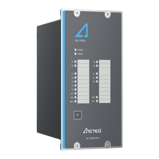
• one (1) binary output (24 V DC) • one (1) system failure output • eighteen (18) indication LEDs • one (1) push-button. Figure. 3.3. - 6. Arc protection unit AQ-110PLV. Figure. 3.3. - 7. Arc protection unit AQ-110FLV. 3.4. Simplified block diagram © Arcteq Relays Ltd... - Page 15 A A Q Q -110xL -110xLV V Version: 1.00 The figures below presents the main components that can be found in the AQ-110xLV units (AQ-110PLV and AQ-110FLV). Figure. 3.4. - 8. Simplified block diagram of AQ-110PLV. © Arcteq Relays Ltd...
- Page 16 A A Q Q -110xL -110xLV V Version: 1.00 Figure. 3.4. - 9. Simplified block diagram of AQ-110FLV. © Arcteq Relays Ltd...
-
Page 17: Operation And Config Tion And Configura Uration Tion
A system A configuration mismatch has been Verify the system condition (see ERROR The system is failure has detected. Protection is partially the "System self-supervision" and (red) healthy. occured. operational. "Troubleshooting" chapters). © Arcteq Relays Ltd... -
Page 18: Push-Button (Set)
SET, and it can be used for all operational functions. The push- button is used for setting up the system (also known as auto-configuration), for resetting the indicator LEDs and the latched output relays, as well as for checking the input connection. © Arcteq Relays Ltd... -
Page 19: System Setup (Auto-Configuration)
I> trimmer (see the image below). You can get an accurate setting by injecting the desired set current into the phase current inputs of the unit and by simultaneously adjusting the trimmer until the phase current indicator LEDs are lit. © Arcteq Relays Ltd... -
Page 20: Dip Switch Settings
Figure. 4.5. - 12. DIP switch diagram for AQ-110PLV (left) and AQ-110FLV (right). © Arcteq Relays Ltd... - Page 21 (AQD) control. The Tx terminal of S5 sends a test pulse and the arc quenching as the fiber loop signal to the quenching system. system (AQD) control. sensor function. Only in y in A A Q Q -110P! -110P! © Arcteq Relays Ltd...
-
Page 22: Scheme Selection
AQ-SAS™ booklet (can be found at arcteq.fi/downloads/). Please note that there are four booklets: two are for schemes based on IEC standards (MV and LV versions) and the other two for schemes based on ANSI standards (MV and LV versions). - Page 23 1) When the DIP switch SW2: 4 is set to "FAST", the trip relay is activated without the CBFP function. When the DIP switch SW2: 4 is set to "CBFP", the CBFP function activates the trip relay for longer than what is set in the CBFP time setting (100 ms or 150 ms). © Arcteq Relays Ltd...
- Page 24 1) When the DIP switch SW2: 4 is set to "FAST", the trip relay is activated without the CBFP function. When the DIP switch SW2: 4 is set to "CBFP", the CBFP function activates the trip relay for longer than what is set in the CBFP time setting (100 ms or 150 ms). © Arcteq Relays Ltd...
-
Page 25: Non-Volatile Memory
This feature is especially important if tripping causes the unit to lose its auxiliary power. The non-volatile memory does not require a power supply to maintain the information and it retains the settings and the indications permanently without power. © Arcteq Relays Ltd... -
Page 26: Ar 5. Arc Sensors C Sensors
Please remember to reattach the cover once the wires have been installed. NOTE! The AQ-01 point sensor does no not t come with a connection cable! © Arcteq Relays Ltd... -
Page 27: Arc Light And Pressure Point Sensor Aq-02
20 m, 25 m, 30 m, 35 m, 40 m). It is not recommended to cut or splice the cable on-site. However, if cutting or splicing is necessary due to the cable breaking, please contact your nearest Arcteq representative for instructions. -
Page 28: Arc Light Fiber Optic Loop Sensor Aq-07
When requested, the ends of an AQ-07 cable can be covered with black rubber to avoid light detection outside the protected zone (see the figure below). The covered area can be as large or small as necessary. For more information, please consult your nearest Arcteq representative. Figure. 5.4. - 16. AQ-07 sensor with covered ends. -
Page 29: Arc Light Fiber Optic Loop Sensor Aq-08
It is not recommended to cut or splice the cable on-site. However, if cutting or splicing is necessary due to the cable breaking, please contact your nearest Arcteq representative for instructions. The fixed light intensity threshold of an AQ-08 sensor is 8,000 lux. The sensor does not require further settings by the user. -
Page 30: Connecting Sensors
Please note that AQ-07 and AQ-08 glass fibers can be covered with additional tubing, if the fiber sensor's placing requires the blocking of unwanted light activation. For more detailed instructions on both the installation and the tubing processes, please refer to the "Connecting sensors" chapter in the AQ-0x instruction booklet (arcteq.fi/downloads). © Arcteq Relays Ltd... -
Page 31: S 6. Sy Y St Stem Self-Super Em Self-Supervision Vision
If at least one of the phases remains above 0.2 × I while the others are at zero, the unit issues an open CT alarm: the SF relay is released, the "Error" LED is turned on and the LED of the faulty phase(s) starts blinking. © Arcteq Relays Ltd... -
Page 32: Connections
A A Q Q -110xL -110xLV V Version: 1.00 7. Connections Figure. 7. - 18. Rear terminals of AQ-110PLV. © Arcteq Relays Ltd... - Page 33 A A Q Q -110xL -110xLV V Version: 1.00 Figure. 7. - 19. Connections of the AQ-110PLV (with SF in de-energized position). Figure. 7. - 20. Rear terminals of AQ-110FLV. © Arcteq Relays Ltd...
-
Page 34: Outputs
(for more information, please refer to the "DIP switch settings" chapter). The output’s direction of rotation is as follows: the signal goes in the even pin and out from the odd pin (see the image below, as detailed in the unit’s side sticker). © Arcteq Relays Ltd... -
Page 35: Binary Outputs
AQ-110FLV has three (3) arc fiber loop sensor channels: S1, S2 and S3. Each channel has a transceiver (Tx) terminal and a receiver (Rx) terminal. Also, there is an additional transceiver (Tx) terminal available for arc quenching system control. © Arcteq Relays Ltd... -
Page 36: Binary Inputs
Version: 1.00 For more information on sensors, please refer to the "Arc sensors" chapter as well as to the AQ-0x instruction booklet which can be found on Arcteq's website (https://www.arcteq.fi/downloads/). 7.2.3. Binary inputs Both AQ-110x variants (MV and LV) contain two (2) binary inputs, BI1 and BI2. -
Page 37: Testing Esting
10. Activate the camera flash within 30 cm (12 inches) of the point sensor unit but do not activate the binary input used for the overcurrent condition (I>). 11. Verify that no trip has occured and only the indicator LED of the sensor activation is lit. © Arcteq Relays Ltd... -
Page 38: Testing The Cbfp Function
If you want to have more information of these tests, please refer to the routine test reports sent with the AQ-110 unit and/or consult your nearest Arcteq representative for the type test reports. - Page 39 A A Q Q -110xL -110xLV V Version: 1.00 © Arcteq Relays Ltd...
-
Page 40: T 9. Tr R Oubleshoo Oubleshooting Ting
Check the set current threshold (see the "Current threshold settings" chapter for is continuously lit. more information). The current measurent's indicator LED is Check that the connections of the three phase currents are correct (see the blinking. "System self-supervision" for more information). © Arcteq Relays Ltd... -
Page 41: Technic Echnical Da Al Data Ta
- continuous - make and carry for 3 s - make and carry for 0.5 s 15 A Breaking capacity DC* 1 A/110 W Contact material Semiconductor *) When the time constant L/R = 40 ms. © Arcteq Relays Ltd... -
Page 42: System Failure Relay
IP 60 Sensor cable specification Shielded twisted pair 0.75 mm (AWG: 20) Maximum sensor cable length (per channel) 200 m Operating temperature –20…+85 ºC AQ-02 point sensor 8,000 lux Light intensity threshold 25,000 lux 50,000 lux © Arcteq Relays Ltd... -
Page 43: Disturbance Tests
AQ-08 fiber optic loop sensor Material Covered glass fiber Light intensity threshold 8,000 lux Cable length (min…max) 3…15 m Cable diameter 1.2 mm Detection radius 360º Bending radius 1 cm Operating temperature –40…+125 ºC 10.6. Disturbance tests Electromagentic compatibility test © Arcteq Relays Ltd... -
Page 44: Voltage Tests
- front IP 50 - back IP 20 Dimensions (W × H × D): - device 102 × 177 × 162 mm - package 230 × 120 × 210 mm 1.2 kg Weight 1.5 kg (with package) © Arcteq Relays Ltd... -
Page 45: Ordering Inf Dering Informa Ormation Tion
A A Q Q -110xL -110xLV V Version: 1.00 11. Ordering information AQ-110xLV current measurement and arc sensing unit AQ-0x point sensors AQ-0x fiber optic loop sensors © Arcteq Relays Ltd... - Page 46 -110xLV V Version: 1.00 Accessories Order code Description Note Manufacturer AQX099 Wall bracket For AQ-101, AQ-101S and AQ-102 units (MV and LV). Arcteq Ltd. AQX100 Wall bracket For AQ-103 and AQ-110x variants (MV and LV). Arcteq Ltd. © Arcteq Relays Ltd...
-
Page 47: Contact And R
Manufacturer Arcteq Relays Ltd. Visiting and postal address Kvartsikatu 2 A 1 65300 Vaasa, Finland Contacts Phone: +358 10 3221 370 Fax: +358 10 3221 389 Website (general): arcteq.fi Website (technical support): support.arcteq.fi E-mail (sales): sales@arcteq.fi © Arcteq Relays Ltd...
Need help?
Do you have a question about the AQ-110 LV Series and is the answer not in the manual?
Questions and answers