Table of Contents
Advertisement
Quick Links
Advertisement
Table of Contents

Summary of Contents for Arcteq AQ-0 Series
- Page 1 AQ-0x Arc sensors Instruction manual...
-
Page 3: Table Of Contents
4.1 Sensors ..........................15 5 Or 5 Ordering inf dering informa ormation tion ..............................................17 6 Contact and r 6 Contact and re e f f er erence inf ence informa ormation tion......................................18 © Arcteq Relays Ltd IM00047... - Page 4 Nothing contained in this document shall increase the liability or extend the warranty obligations of the manufacturer Arcteq Relays Ltd. The manufacturer expressly disclaims any and all liability for any damages and/or losses caused due to a failure to comply with the instructions contained herein or caused by persons who do not fulfil the aforementioned requirements.
- Page 5 A A Q Q -0x Instruction manual Version: 1.04 Copyright Copyright © Arcteq Relays Ltd. 2022. All rights reserved. © Arcteq Relays Ltd IM00047...
- Page 6 This booklet only describes the AQ-0x series sensors used in the arc protection system in conjunction with other units from the AQ 100 series. It is important to read the instruction manuals for the individual AQ-100 units as well! © Arcteq Relays Ltd IM00047...
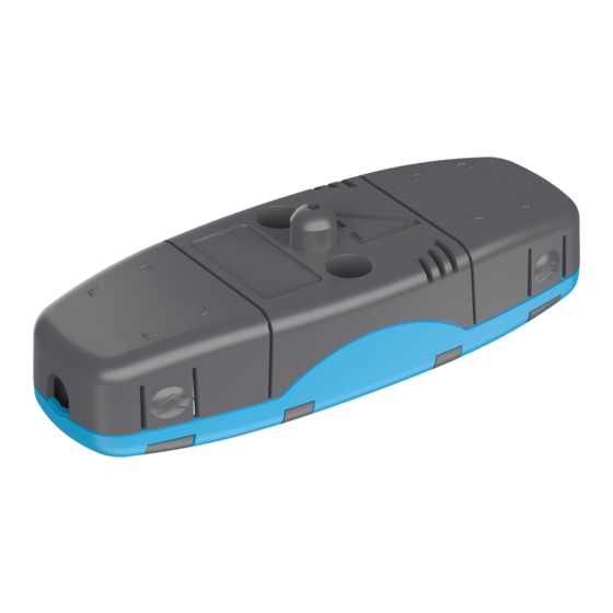
- Page 7 Installing a connection cable is simple as each end of the sensor has a detachable cover over the cable connectors. Please remember to reattach the cover once the wires have been installed. NOTE! The AQ-01 point sensor does no not t come with a connection cable! © Arcteq Relays Ltd IM00047...
- Page 8 AQ-07 sensors can be ordered in pre-manufactured lengths of 3…50 meters (3 m, 5 m, 10 m, 15 m, 20 m, 25 m, 30 m, 35 m, 40 m, 45 m, 50 m). The fixed light intensity threshold of an AQ-07 sensor is 8,000 lux. The sensor's detection radius is 360 degrees. © Arcteq Relays Ltd IM00047...
-
Page 9: Arc Light Fiber Optic Loop Sensor Aq-06
The covered area can be one (1) or two (2) meters by default; if other lengths are required, please consult the Arcteq sales team. You can find the "Contact and reference information" page at the end of this manual. - Page 10 Yes (when the unit is Yes (when the unit is Yes (when the unit is A A Q Q -110FL -110FLV V equipped with the fiber equipped with the fiber equipped with the fiber option) option) option) © Arcteq Relays Ltd IM00047...
-
Page 11: Connecting Sensors
3. Connect the other end of the cable into a sensor channel of an appropriate AQ-100 unit (AQ-101 variants, AQ-103 variants and AQ-110P, or their LV versions). See the image below, where the cable is connected to an AQ-101 unit. © Arcteq Relays Ltd IM00047... - Page 12 Figure. 3.1 - 6. Front panel check. 5. Attach the connector back into its slot in the sensor PCB (see the red arrow in the image below; the connector is already in place on the right side). © Arcteq Relays Ltd IM00047...
- Page 13 Figure. 3.1 - 7. Reattaching the connector into the sensor PCB. 6. Now, the "Error" LED should be lit and the LED for the appropriate sensor channel should start blinking ("S1", for example; see the image below). Figure. 3.1 - 8. LEDs. © Arcteq Relays Ltd IM00047...
- Page 14 You can connect a maximum of three (3) point sensor in a series on one sensor channel (see the image below). Please note that the AQ-103 and AQ-103LV units are an exception: you can only have one (1) sensor per channel! Figure. 3.1 - 10. Three sensors connected in series. © Arcteq Relays Ltd IM00047...
-
Page 15: Fiber Loop Sensors
2. Install protective covers in the holes to ensure the sensor cable remains unharmed by rough edges. 3. Run the sensor cable through the holes and along the protected area. Fasten it to the compartment walls with cable clips or some other appropriate anchoring method. © Arcteq Relays Ltd IM00047... - Page 16 Instruction manual Version: 1.04 4. Turn the black and blue receiver (“Rx”) and transceiver (“Tx”) screws counter-clockwise and plug in the sensor cable terminals. 5. Turn the screws clockwise to secure the terminals in their place. © Arcteq Relays Ltd IM00047...
-
Page 17: Technic Echnical Da Al Data Ta
Table. 4.1 - 6. Technical data for the AQ-06 fiber optic loop sensor. Material Plastic fiber Light intensity threshold 8,000 lux Cable length (min…max) 3…40 m Cable diameter 1.0 mm Detection radius 360º Bending radius 5 cm Operating temperature –40…+85 ºC © Arcteq Relays Ltd IM00047... - Page 18 Table. 4.1 - 8. Technical data for the AQ-08 fiber optic loop sensor. Material Covered glass fiber Light intensity threshold 8,000 lux Cable length (min…max) 3…15 m Cable diameter 1.2 mm Detection radius 360º Bending radius 1 cm Operating temperature –40…+125 ºC © Arcteq Relays Ltd IM00047...
- Page 19 A A Q Q -0x Instruction manual Version: 1.04 5 Ordering information AQ-0x point sensors AQ-0x fiber optic loop sensors © Arcteq Relays Ltd IM00047...
- Page 20 Arcteq Relays Ltd. Visiting and postal address Kvartsikatu 2 A 1 65300 Vaasa, Finland Contacts Phone: +358 10 3221 370 Website: arcteq.fi Technical support: support.arcteq.fi +358 10 3221 388 (EET 9:00 – 17.00) E-mail (sales): sales@arcteq.fi © Arcteq Relays Ltd IM00047...


Need help?
Do you have a question about the AQ-0 Series and is the answer not in the manual?
Questions and answers