
Related Manuals for Hoval TopVent TV Series


Summary of Contents for Hoval TopVent TV Series
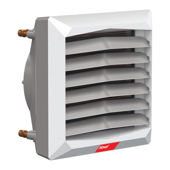
- Page 1 TopVent ® Design, installation and operation TopVent ® Recirculation unit for heating spaces up to 6 m in height...
-
Page 2: Table Of Contents
TopVent ® Content Design, installation and operation 1 Use 1.1 Intended use ..............3 1.2 User group ..............3 2 Safety 2.1 Symbols ................. 4 2.2 Operational safety ............4 3 Construction and operation 3.1 Unit construction ............5 3.2 Operating modes ............6 4 Technical data 4.1 Application limits ............ -
Page 3: Use
TopVent ® Design, installation and operation 1 Use 1.1 Intended use TopVent TV units are recirculation units intended for heating spaces up to 6 m in ® height. They have the following functions: ■ Heating (with connection to a hot water supply) ■... -
Page 4: Safety
TopVent ® Safety Design, installation and operation 2 Safety 2.1 Symbols Caution This symbol warns against risk of injury. Please heed all instructions designated by this symbol to prevent injuries and/or death. Attention This symbol warns against property damage. Please heed the respective instructions to prevent risk of damage to the unit and its functions. -
Page 5: Construction And Operation
TopVent ® Construction and operation Design, installation and operation 3 Construction and operation The TopVent ® TV is used to heat in recirculation operation; it was developed specially for use in rooms up to 6 m in height. The unit is installed on the wall or under the ceiling. -
Page 6: Operating Modes
TopVent ® Construction and operation Design, installation and operation 3.2 Operating modes A room temperature controller with or without a timer regulates the operation of the unit. EasyTronic EC The EasyTronic EC is a room temperature controller with a timer. A maximum of 10 TopVent ®... - Page 7 TopVent ® Construction and operation Design, installation and operation EasyTronic TV The EasyTronic TV is a room temperature controller without a timer. A maximum of 8 TopVent ® units can be connected to 1 controller. Function ■ Recording the room temperature with the integrated temperature sensor ■...
-
Page 8: Technical Data
TopVent ® Technical data Design, installation and operation 4 Technical data 4.1 Application limits Maximum operating pressure 1600 Maximum heating medium temperature °C Maximum supply air temperature °C Maximum extract air temperature °C The units cannot be used in: Areas where there is danger of explosion ■ ■ Places with a corrosive or aggressive environment ■ Damp locations ■... -
Page 9: Sound Data
TopVent ® Technical data Design, installation and operation 4.4 Sound data Type TV-2 TV-4 TV-5 Sound pressure level (at a distance of 5 m) dB(A) Total sound power level dB(A) Reference: room volume 1500 m³ Table 7: Sound levels 4.5 Dimensions and weights Return Flow Type TV-2 TV-4 TV-5 Water content of the coil 1.12... -
Page 10: Transport And Installation
TopVent ® Transport and installation Design, installation and operation 5 Transport and installation Caution Risk of injury from incorrect handling. Transport, assembly and installation work may only be performed by specialists. Observe safety and accident prevention regulations. 5.1 Delivery TopVent ®... -
Page 11: Installation
TopVent ® Transport and installation Design, installation and operation 5.3 Installation Caution Risk of injury caused by falling load and improper handling. During installation: – Wear protective equipment (safety helmet, safety goggles, safety shoes). – Do not stand under suspended loads. –... -
Page 12: Hydraulic Installation
TopVent ® Transport and installation Design, installation and operation 5.4 Hydraulic installation ■ Connect the heating coil according to the hydraulic circuit diagram. ■ Depending on local conditions, check whether compensators for linear expan- sion are required for the supply and return lines. ■... -
Page 13: Electrical Installation
TopVent ® Transport and installation Design, installation and operation 5.5 Electrical installation Caution Danger of electric shocks. The electrical installation is to be carried out only by a qualified electrician. Please note the following: ■ Observe all relevant regulations. ■ Choose the dimensions of the cable cross sections in line with the applicable regulations. - Page 14 TopVent ® Transport and installation Design, installation and operation white black yellow/green blue brown white black yellow/green blue brown Fig. 8: Wiring diagram TopVent ® TV with EasyTronic EC 4 216 284-en-05...
- Page 15 TopVent ® Transport and installation Design, installation and operation white black yellow/green blue brown white black yellow/green blue brown Fig. 9: Wiring diagram TopVent ® TV with EasyTronic TV 4 216 284-en-05...
- Page 16 TopVent ® Transport and installation Design, installation and operation Installation EasyTronic EC ■ Follow the installation instructions included. Installation EasyTronic TV ■ Install the room temperature controller: – In the occupied area, at a height of about 1.5 m – Not near sources of heat or cold (windows, doors, machines, etc.) –...
-
Page 17: Operation
TopVent ® Operation Design, installation and operation 6 Operation 6.1 Initial commissioning Attention Risk of damage to property as a result of performing initial commissioning on your own authority. Initial commissioning must be performed by the manufacturer’s customer service technicians . Preparing for initial commissioning: Checklist: ■... -
Page 18: Maintenance And Repair
TopVent ® Design, installation and operation 7 Maintenance and repair Caution Risk of injury from incorrect work. Maintenance work must be carried out by trained personnel. 7.1 Safety Before performing any work on the unit: ■ Turn the on-site main switch to the ‘Off’ position and secure it against being switched back on. -
Page 19: Dismantling
TopVent ® Dismantling Notes Design, installation and operation 8 Dismantling Caution Risk of injury caused by falling load and improper handling. – Wear protective equipment (fall protection, safety helmet, safety shoes). – Do not stand under suspended loads. ■ Disconnect the power supply to the unit. ■... - Page 20 TopVent ® Contact Contact Operating instructions International Hoval Aktiengesellschaft 9490 Vaduz Liechtenstein Tel. +423 399 24 00 info.klimatechnik@hoval.com www.hoval.com United Kingdom Hoval Ltd. Northgate, Newark Notts NG24 1JN Tel. 01636 672711 hoval@hoval.co.uk www.hoval.co.uk 4 216 284-en-05...
Need help?
Do you have a question about the TopVent TV Series and is the answer not in the manual?
Questions and answers