
Related Manuals for Polon-Alfa TUN-38Ex


Summary of Contents for Polon-Alfa TUN-38Ex
- Page 1 TUN‐38Ex Intrinsically Safe HEAT DETECTOR Installation and Maintenance Manual IK‐E280‐001GB IIIC Issue ...
- Page 2 2 IK‐E280‐001GB The TUN‐38Ex heat detector covered by the present manual, complies with the requirements of the following European Union Directives: CPD 89/106/EWG on construction materials; LVD 2006/96/WE on electric equipment to be used in determined voltage range; EMC 2004/108/WE on electromagnetic compatibility; ATEX 94/9/WE on equipment and protective systems intended for use in potentially explosive atmospheres. The TUN‐38Ex Heat Detector has been approved with the EC‐Certificate of Conformity No. 1438/CPD/0025 issued by the Fire Protection Science and Research Centre (CNBOP) Józefów, Poland, a EU notified authority No. 1438, confirming its compliance with the requirements of PN‐EN 54‐ 5:2003 standard. ...
-
Page 3: Technical Specifications
1 PURPOSE is designed for detection of fire hazard or fire appearance The TUN‐38Ex Heat Detector warning in closed rooms, where during the first phase of fire an occurrence of temperature rise may be observed, or where – due to various reasons – temperature may exceed the set fire danger level. It is provided for working together in fire detecting lines with control panels manufactured by POLON‐ALFA or by other producers that obtained POLON‐ALFA’s compatibility confirmation. The detector’s operational temperature is between ‐ 25 °C and + 50 °C for A1 class and + 65 °C for B class. The TUN‐38Ex heat detectors are connected to fire detecting lines through intrinsically safe barrier or separator of the following parameters: Uo ≤ 25 V, Io ≤ 99 mA. The detectors are installed in rooms and zones qualified as 1 and 2 explosive hazard category resulting from potential explosion danger ... -
Page 4: Safety Conditions
3 INSINTRIC SAFETY PARAMETERS Supply line marginal parameters: Maximum input voltage 25 V Maximum input current 99 mA Maximum input power 0,613 W Maximum inner capacity 16,5 nF Maximum inner inductance 0* Maximum outer capacity ... -
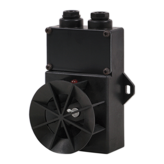
Page 5: Construction Description
IK‐E280‐001GB 5 Special attention shall be given to stability of ladders, elevators, lifts, etc. Any electric tools shall be used strictly obeying the safety rules stated in instruction manuals by manufacturers. 4.3 Anti‐dusting eye protection It is obligatory to use protective anti‐dusting glasses and masks during detector installation works that produce high amount of dust, such as hole drilling in ceilings. 5 CONSTRUCTION DESCRIPTION Casing Junction cover Cover Optical indicator... - Page 6 6 IK‐E280‐001GB Table 1 Air temperature A1 Class B Class increase rate Low activation Top activation Low activation Top activation in relation to normal time limit time limit time limit time limit operating temperature K/min min s min s min s min s 1 29 00 40 20 29 00 46 00 3 7 13 13 40 7 ...
-
Page 7: Detector Installation
IK‐E280‐001GB 7 Temperature of activation Speed of growth of temperature Chart 1 7 DETECTOR INSTALLATION Determine the detector class with the cramps that are accessible after the cover removal. Cramp positions corresponding to various classes is shown on Figure 2. Fig. 2 Cramp positioning for various detector class (example of A1R‐H). Detectors shall be connected to detecting lines in accordance with Figure 3. ... -
Page 8: Detector Maintenance
8 IK‐E280‐001GB Fig. 3 Exemplary TUN‐38Ex detector connection to detecting line. It is obligatory to utilize intrinsically safe barrier or separator (named in the control panel Operational Manual) in intrinsically safe detecting lines. After installing all detectors, the control panel or supplying apparatus should be switched on. Every detector must be individually checked. It is not recommend to warm up more than one detector in one detecting line. In case more than three detectors in one detecting line are warmed up at the same time a false damage (short circuit) signal ... - Page 9 IK‐E280‐001GB 9 Fig. 4 TUN‐38Ex detector basic dimensions IK‐E280‐001GB/07.2009 ...
Need help?
Do you have a question about the TUN-38Ex and is the answer not in the manual?
Questions and answers