Makita GS5000 Technical Information
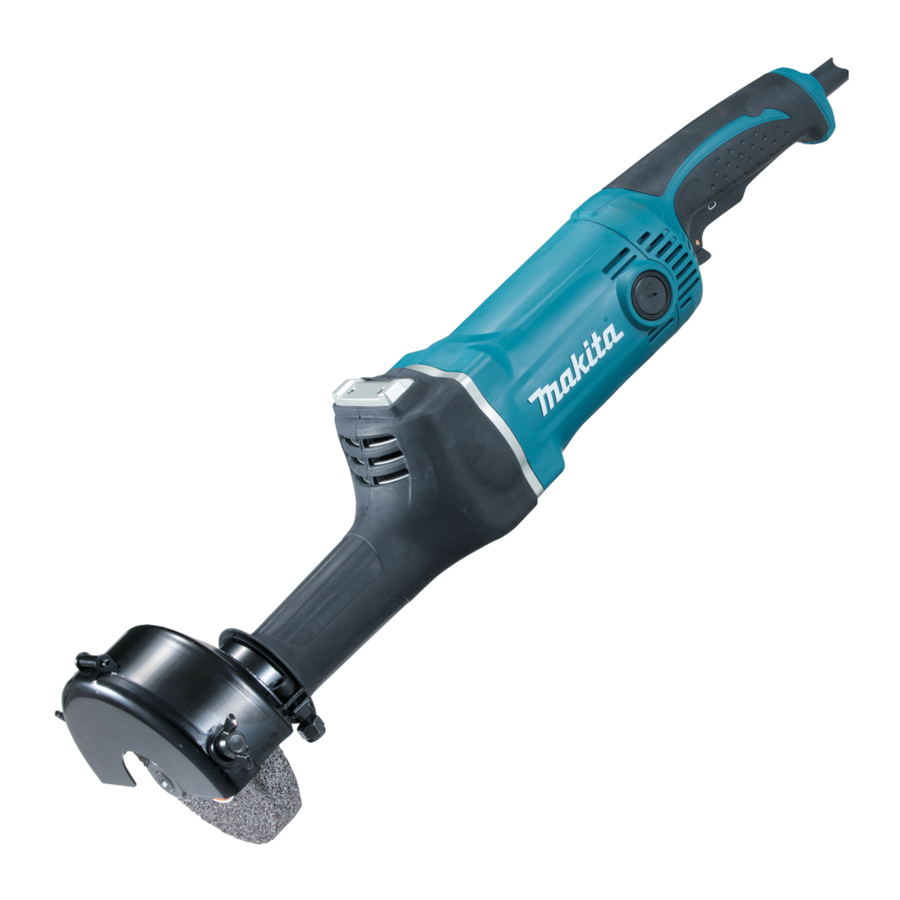
Straight grinder
Hide thumbs
Also See for GS5000:
- Instruction manual (77 pages) ,
- Instruction manuals (13 pages) ,
- Instruction manual (12 pages)
Advertisement
T
ECHNICAL INFORMATION
Model No.
Description
C
ONCEPT AND MAIN APPLICATIONS
Models GS5000 and GS6000 are double insulated versions of
model 9105 125mm (5") straight grinder.
The high performance and handling is the same as model 9105.
Featuring are;
• Improved gear durability by change of grease and modification
on the inside of gear housing.
• Ergonomically design handle and barrel for added
extra maneuverability.
Wheel size is:
125mm (5'') for Model GS5000
150mm (6'') for Model GS6000
S
pecification
Voltage (V)
110
120
220
230
240
Specification
Wheel size*
:
3
mm (")
No load speed: min.
Soft start feature
Rubberized soft grip
Protection against electric shock
Power supply cord: m (ft)
Weight according to
EPTA-Procedure 01/2003
*1 the model with the wheel that is in compliance with the regulations.
*2 the model with the wheel that is not in compliance with the regulations.
*3 Grinding wheels of Model 9105 cannot be used because of the wheel rotation speed limit.
*4 with Wheel cover, Inner flange, Outer flange, Lock nut
S
tandard equipment
Hex wrench 6 ............................................. 1
Wrench holder 5.6 ...................................... 1
Wrench 24 .................................................. 1 (for some country only)
Lock nut wrench 35 .................................... 1 (for some country only)
Grinding wheel ........................................... 1 (for some country only)
Note: The standard equipment for the tool shown above may vary by country.
O
ptional accessories
Hanger set
Grinding wheels
Dust cover attachment set
GS5000, GS6000
Straight Grinders 125mm (5"), 150mm (6")
Current (A)
Cycle (Hz)
7.2
50/ 60
7.0
50/ 60
3.6
50/ 60
3.5
50/ 60
3.3
50/ 60
Model No.
Diameter
Hole diameter
Max. thickness
¹=rpm
ˉ
5.0 (11.1)*
: kg (lbs)
*4
Model No.
Length (L)
Width (W)
Height (H)
*1: the model that is in compliance with the regulations.
*2: the model that is not in compliance with the regulations.
Continuous Rating (W)
Input
750
---
750
750
750
GS5000
125 (5)
20 (3/4), 12.7 (1/2)
20 (3/4)
5,600
No
Yes
Double insulation
Australia, Brazil: 2.0 (6.6), Other countries: 2.5 (8.2)
, 4.9 (10.7)*
1
2
PRODUCT
L
H
W
The above drawing is GS5000 that is in
compliance with the regulations.
Dimensions: mm (")
GS5000
GS6000
590 (23-1/4)*
, 588 (23-1/8)*
1
189 (7-7/16)*
,
216 (8-1/2)*
1
143 (5-5/8)*
171 (6-3/4)*
2
116 (4-9/16)*
,
130 (5-1/8)*
1
118 (4-5/8)*
120 (4-3/4)*
2
Max. Output (W)
Output
400
450
400
400
400
GS6000
150 (6)
5.2 (11.5)*
, 5.0 (11.1)*
1
P 1/ 9
2
,
1
2
,
1
2
700
700
850
850
850
2
Advertisement
Table of Contents

Related Manuals for Makita GS5000


Summary of Contents for Makita GS5000
- Page 1 Model No. Description Straight Grinders 125mm (5"), 150mm (6") ONCEPT AND MAIN APPLICATIONS Models GS5000 and GS6000 are double insulated versions of The above drawing is GS5000 that is in model 9105 125mm (5") straight grinder. compliance with the regulations.
-
Page 2: Necessary Repairing Tools
Wrench for Bearing retainer removing/ assembling Bearing retainer 31-48 from/ to Gear housing [2] LUBRICATION Apply Makita grease N No.1 to the following portions designated with the black triangle to protect parts and product from unusual abrasion. Item No. Description... - Page 3 P 3/ 9 epair [3] DISASSEMBLY/ASSEMBLY [3] -1. Helical gear 47, Ball bearings 6203LLB and 6204LLB DISASSEMBLING Note: Disassembling can be done without removing Insulation cover completely. (1) Remove Wheel cover and Grinding wheel. (2) Separate Gear housing from Motor housing as drawn in Fig. 2. Fig.
- Page 4 P 4/ 9 epair [3] DISASSEMBLY/ASSEMBLY [3] -1. Helical gear 47, Ball bearings 6203LLB and 6204LLB (cont.) DISASSEMBLING (4) Ring 17 makes approx. 5 mm gap between Ball bearing 6203LLB and Helical gear 47. The gear can be disassembled by using this gap. (Fig. 4) Fig.
- Page 5 P 5/ 9 epair [3] DISASSEMBLY/ASSEMBLY [3] -1. Helical gear 47, Ball bearings 6203LLB and 6204LLB (cont.) ASSEMBLING (1) Assemble Spindle section as drawn in Fig. 5. Fig. 5 3. Press-fit Helical gear 47 onto Spindle with 1R031. 1. While standing Spindle on 1R037, assemble Ball bearing 6203LLB with 1R031.
- Page 6 P 6/ 9 epair [3] DISASSEMBLY/ASSEMBLY [3] -2. Armature, Ball bearing 6201DDW DISASSEMBLING (1) Separate Gear housing from Gear housing cover. (Refer to Fig. 2) (2) Disassemble Armature as drawn in Fig. 7. (3) Remove Ball bearing 6201DDW as drawn in Fig. 8. Fig.
-
Page 7: Insulation Cover
P 7/ 9 epair [3] DISASSEMBLY/ASSEMBLY [3] -3. Insulation cover ASSEMBLING Insulation cover can be assembled as drawn in Fig. 9. Fig. 9 1. Apply soapsuds to the surface of Gear housing. 2. Apply soapsuds to the inside of Insulation cover. Insulation cover Gear housing 3. -
Page 8: Circuit Diagram
P 8/ 9 ircuit diagram Fig. D-1 Color index of lead wires' sheath Black White Power supply cord Blue lead wire is used Brown lead wire is used for some countries for some countries instead of White. instead of Black. Noise suppressor Switch Noise suppressor is not used for... -
Page 9: Wiring Diagram
P 9/ 9 iring diagram Fig. D-2 Wiring of Field lead wires Note: Pull out Field lead wires (white, black) so that they are tightened in Motor housing. Route Field lead wire (white) Fix Field lead wire (black) inside of the hook. with Lead wire holder.
Need help?
Do you have a question about the GS5000 and is the answer not in the manual?
Questions and answers